Connection examples – NORD Drivesystems TI 275281206 User Manual
Page 6
IO-Extension
– SK TU4-IOE-M12
6
TI 275281206 - 4912
The special wiring of the M12 round plug connector enables connection of both single and double
sensors, which are equipped with normal M12 system connectors in the standard sensor/actuator
configuration.
With the use of M12 round plug connectors, the terminal bar connectors for the digital inputs
(connection unit of the option) must not be used.
The LEDs between the plug connectors indicate the switching status of the IOs (top, from left to right
DIN1, DIN3, DOUT1 / bottom, from left to right DIN2, DIN4, DOUT2).
Pos : 12 /T echnisc he I nf ormati onen/I O - Er weit er ung/ Ans chl uss beis piel e [IO E Allgemei n] @ 2\ mod_1352736753713_388. doc x @ 51105 @ 6 @ 1
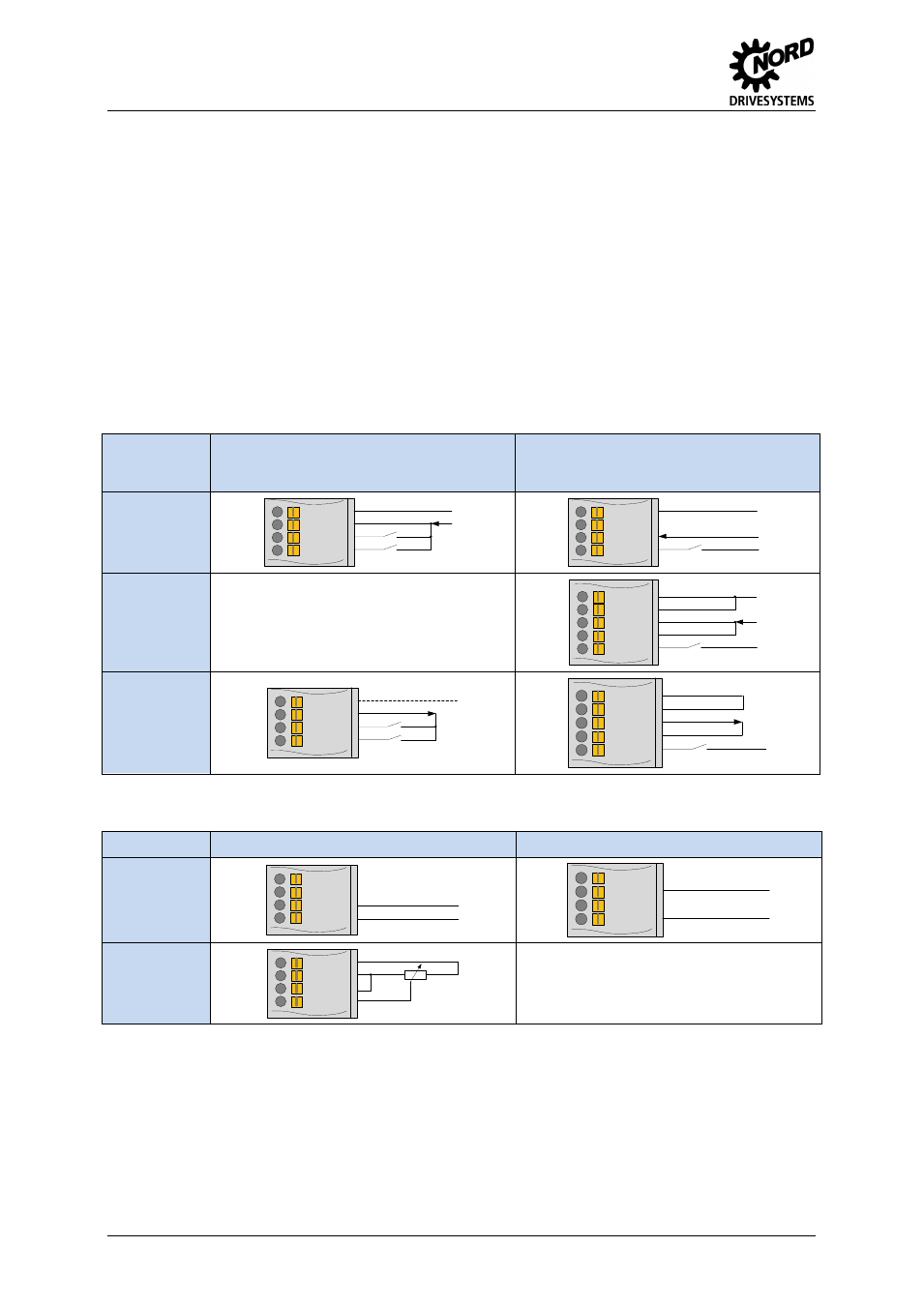
Connection examples
The following connection examples are generally applicable for NORD IO modules. The number or
type of the available IOs and their configuration on the terminal rail varies according to the module.
The actual availability or the designation of the individual contacts should be obtained by reference to
the description of the connections. The technical data (e.g. load capacity) must be taken into account.
Digital signals
Control
voltage
source
Digital input
Digital output
External
supply
GND/0V
VI 24V
DIN
DIN
GND2/0V2
DOUT
VI 24V2
GND2/0V2
VI 24V
DOUT
VI 24V2
GND/0V
Internal supply
GND/0V
VO 24V
DIN
DIN
GND2/0V2
VO 24V
DOUT
VI 24V2
GND/0V
Analog signals
Signal type*
Analog / Differential input
Analog output
0/2 … 10 V
0/4 … 20 mA
-
10 … 10 V**
VO 10V
AGND/0V
AIN -
AIN +
AGND/0V
AOUT
Potentiometer
(10
kΩ)
0 … 10 V
VO 10V
AGND/0V
AIN -
AIN +
R=10kΩ
* The relevant IOs must be configured via DIP switches according to the form of the signal
** Analog input only