Kaman KD-2300 User Manual
Page 40
KD-2300 Instruction Manual
Appendix B: System Modifications
••••
37
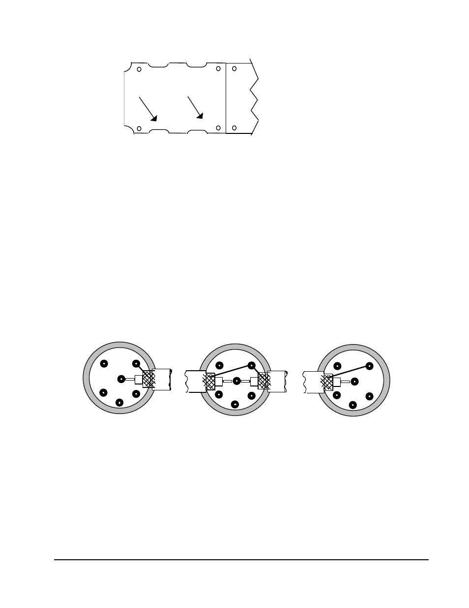
E1 & E2 in
this area
E3, E4, & E5
in this area
Lower PC Board
FOR SLAVE UNITS
~ Locate the jumpers marked E3, E4, and E5 near the connector
end of the PC board. A bold arrow on the silkscreen
highlights this area. Solder a jumper wire between E4 and E5.
~ Locate the jumpers marked E1 and E2. Two bold arrows on
the silkscreen highlight this area. Using a hobby knife,
cut the trace between them. (This removes the crystal
from the oscillator circuit).
~ Reconnect the PC board ribbon cable, re-secure the board
with the four screws, replace the top cover and refasten
it with the eight screws.
POWER AND OUTPUT CABLE
~ To interconnect the oscillators, modify the power plugs by
connecting the coaxial cables between connectors of the units being
synchronized as shown in the figure below.
1
2
3
6
4
5
1
2
3
6
4
5
1
2
3
6
4
5
1. Connect the outer conductor of the coaxial cable to pin 6 of the connector.
2. Connect the shield (braid) of the coaxial cable to pin 5 of the connector.