Synchronization of multiple units – Kaman KD-2300 User Manual
Page 39
36
••••
Appendix B: System Modifications
KD-2300 Instruction Manual
G
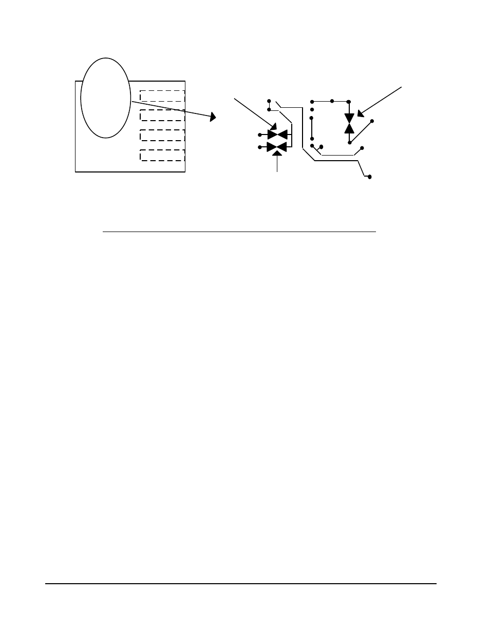
Cut this trace for
maximum s ensitivity
(gain)
L
H
Cut this trace for
least s ensitive offset
(zero) control
Cut this trac e for mid
s ensitive offset
(zero) control
PC BOARD
Synchronization of Multiple Units
When two or more sensors are mounted in close proximity, their electronic
fields may intermix, causing interference in the form of “beat notes”. (The
frequency of the beat notes is the difference between the frequencies of the
oscillator demodulator units, usually 10Hz). This problem is easily solved by
synchronizing the oscillators. You will need to configure the units as master
and slaves, as described below.
FOR BOTH MASTER AND SLAVE UNITS:
~ Remove oscillator-demodulator cover by removing the eight cover screws.
~ Remove the four screws securing the PC board.
~ Flip the PC board up toward the connector end of the housing, being careful
not to strain the interconnection between the boards. This board may be
removed temporarily by unplugging the ribbon cable from the upper PC board.
FOR MASTER UNIT
~ Locate the jumpers marked E3 and E4 near the connector end of the lower
PC board. A bold arrow on the silkscreen highlights this area. Solder a
jumper wire between E3 and E4.
~ Locate the jumpers marked E1 and E2. Two bold arrows on the silkscreen
highlight this area. They should be connected. If they are not connected
(meaning that the unit was previously used as a slave), solder a jumper wire
between them.
~ Reconnect the PC board ribbon cable, re-secure the board with four screws,
replace the top cover and refasten it with the eight screws.