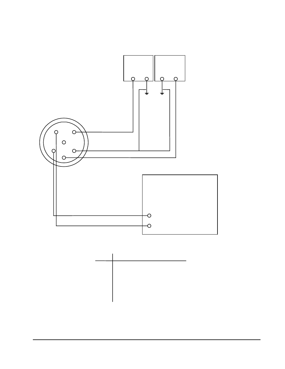
Figure 1 – Kaman KD-2300 User Manual
Page 14
KD-2300 Instruction Manual
Part II: Getting Started
••••
11
15 V
Supply
+
15 V
Supply
-
1
6
5
4
3
2
DVM,
Recorder,
Oscilloscope,
or
Computer Interface
+
-
+ Output
- Output
WIRING DIAGRAM USING TWO SEPARATE 15 V LINEAR POWER SUPPLIES
user
supplied
user
supplied
PIN
1
2
3
4
5
6
+ 15 Vdc (Positive supply input)
Ground (Common supply input)
- 15Vdc (Negative supply input)
+ Output
- Output (Common with ground)
No connection (Sync output)
J1
-
+
Figure 1