Figure 3 – Kaman KDM-8206 User Manual
Page 7
Kaman Precision Products
PART NO: 860515-001
www.kamansensors.com
Last Revised: 6/20/2011
7
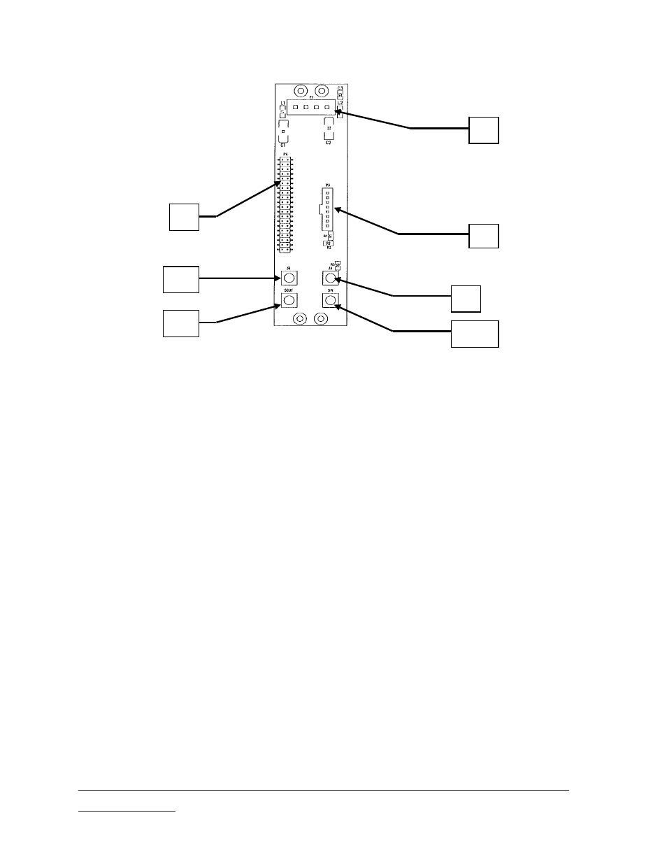
Figure 3
Measuring Channel Back Plane PCB, Rear View
There are two versions of the Back Plane PCB. The Channel 1 version is installed in
the channel 1 position only. The Channel 1 version is not installed if the rack has a
display module, refer to Part 4 of this manual. The Channel 2+ version is installed for
channel 2 and subsequent measuring channels in the rack. Differences between the
two versions are the connectors installed. Connections to the Back Plane PCB are:
J1 Euro connector to Measuring Channel
J2 Connects to subsequent Measuring Channel Back Plane PCB.
JA Sensor input for a single coil sensor. Sensor active coil for a dual coil sensor
JB Sensor inactive coil for a dual coil sensor. Not connected for a single coil
sensor
P1 Input DC power. Only present on channel 1 Back Plane PCB
P2 Connects to previous Measuring Channel Back Plane PCB. Only present on
channel 2+ Back Plane PCB.
P3 Ribbon cable connector. To Back Panel PCB
P4 Dual row terminal strip for optional display module. Refer to Part 4 of this
manual.
SIN Synchronization signal input for optional multi-rack synchronization. Only
present on channel 1 Back Plane PCB
SOUT Synchronization signal output for optional multi-rack synchronization.
Only present on channel 1 Back Plane PCB
P1
P3
JA
JB
SIN
SOUT
P4