Part 2 - rear panel connections, Part 2 rear panel connections, Figure 1 rear panel i/o – Kaman KDM-8206 User Manual
Page 5: Figure 1
Kaman Precision Products
PART NO: 860515-001
www.kamansensors.com
Last Revised: 6/20/2011
5
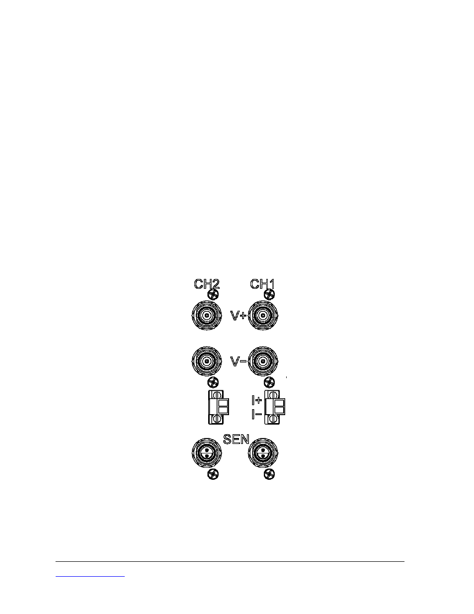
PART 2 - REAR PANEL CONNECTIONS
Refer to Figure 1 below. Twin BNC connectors on the bottom row are for connecting
the Sensors to the rack or enclosure. The rack was configured at the factory to enable
the measuring channel to use a single coil or dual coil sensor. If a measuring channel is
being changed from a single coil sensor to a dual coil sensor, it will be necessary to add
an additional RF cable between the measuring channel backplane board and backpanel
board.
Measuring channel output voltages are available on two rows of (isolated from chassis)
BNC connectors on the back panel.
The upper row (V+) is for single ended outputs.
The upper (V+) and lower (V-) are used for differential outputs. The lower (V-)
connectors are present only if differential voltage output is specified at time of
order.
Measuring channel output current (4-20 mA) is also available on the back panel through
a terminal block. The plug in terminal block may be unplugged, connected to customer-
supplied wire, and plugged back in.
Figure 1
Rear Panel I/O