Figure 8 back panel p4 jumper configuration, Figure 8 – Kaman KDM-8206 User Manual
Page 11
Kaman Precision Products
PART NO: 860515-001
www.kamansensors.com
Last Revised: 6/20/2011
11
For Figures 6 and 7 above, the connections labeled are:
J1 connects to the back plane PCB of Measuring Channel No. 1
P1 input DC power from rack power supply
P3 ribbon cable connection to the front panel display module
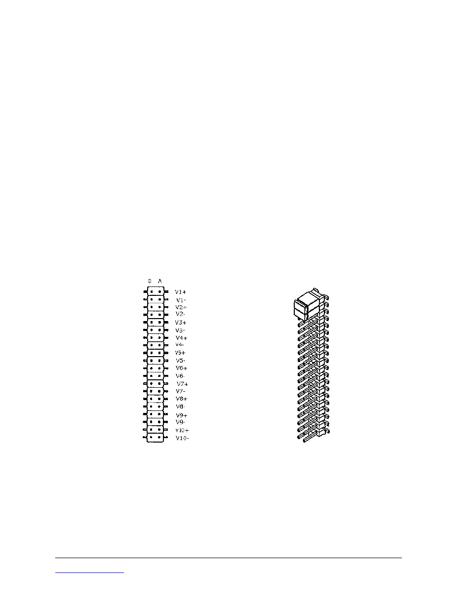
To configure the rack enclosure for the Display Module, jumpers need to be set on
terminal strip P4 on the Back Panel PCB of each Measuring Channel. Placement of
jumpers determines the channel on the Display Module where output from that
Measuring Channel is displayed.
The top two rows of P4 are for Channel 1 on the Display Module and are labeled V1+
and V1-. When jumpers are placed on P4 connecting pins A and B of that of the V1+
and V1- rows, output is routed to the Channel 1 (switch) position on the Display Module.
Rows 3 and 4 (V2+ and V2-) are for Channel 2. Rows 5 and 6 (V3+ and V3-) are for
Channel 3. And so on through V10+ and V10- for Channel 10.
Channel 1 is the Measuring Channel adjacent to the Display Module and channels are
numbered in sequence from left to right when viewed from the front of the rack or
instrument enclosure.
Figure 8
Back Panel P4 Jumper Configuration
Figure 8 is a depiction of P4. The left side is a top view showing the row labels. The
right side of Figure 8 shows P4 with jumpers installed for Measuring Channel 1.