Part 3 - measuring channel connections, Part 3 measuring channel connections, 1 back plane pcb – Kaman KDM-8206 User Manual
Page 6: Figure 2
Kaman Precision Products
PART NO: 860515-001
www.kamansensors.com
Last Revised: 6/20/2011
6
PART 3 - MEASURING CHANNEL CONNECTIONS
Internal wiring for each Measuring Channel in a rack or instrument enclosure is in
modular format. Each Measuring Channel requires:
A Back Plane PCB to connect to the Measuring Channel
A Back Panel PCB for sensor input and analog voltage or current output
A 6 inch interconnecting ribbon cable between back plane and back panel for
output
Interconnecting 6 inch coaxial cable(s) for sensor input. One cable is required for
a single coil sensor. Two cables are required for a dual coil sensor.
3.1 Back Plane PCB
The Back Plane PCB is installed to the horizontal rails inside the rack and secured with
four screws. A Back Plane PCB is required for each Measuring Channel installed in the
rack. Its purpose is to provide all I/O connections to each Measuring Channel, which
are:
Sensor
connections
Input
power
Synchronization
signal
Analog
output
Optional Display Module input signals
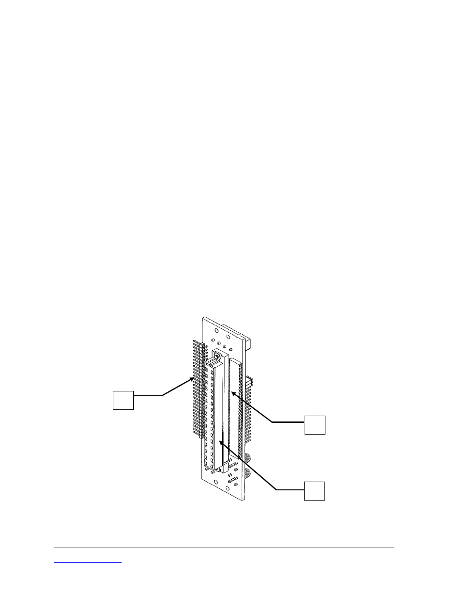
Figure 2
Measuring Channel Back Plane PCB, Front View
P2
J1
J2