Main unit disassembly process, Main unit disassembly flowchart – Acer 1820PT User Manual
Page 61
Chapter 3
51
Main Unit Disassembly Process
IMPORTANT: Cable paths and positioning may not represent the actual model. During the removal and
replacement of components, ensure all available cable channels and clips are used and that the cables are
replaced in the same position.
NOTE: The product previews seen in the disassembly procedures may not represent the final product color or
configuration.
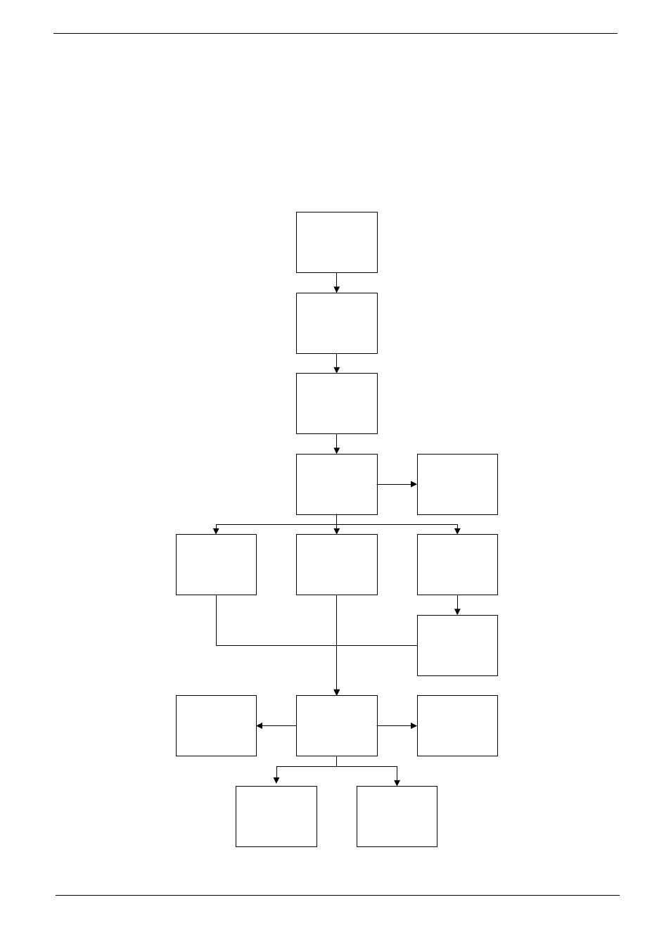
Main Unit Disassembly Flowchart
Remove External
Modules before
proceeding
Remove
Mainboard
Remove
Keyboard
Remove
Upper Cover
Remove
Thermal Module
Remove
LCD Module
Remove
Speaker Module
Remove
I/O Board
Remove
RTC Battery
Remove
Bluetooth Module
Remove
Button Board
Remove
LED Board
Remove
CRT Board
Remove
Hinge Covers
This manual is related to the following products: