Cable – Dwyer 275 User Manual
Page 4
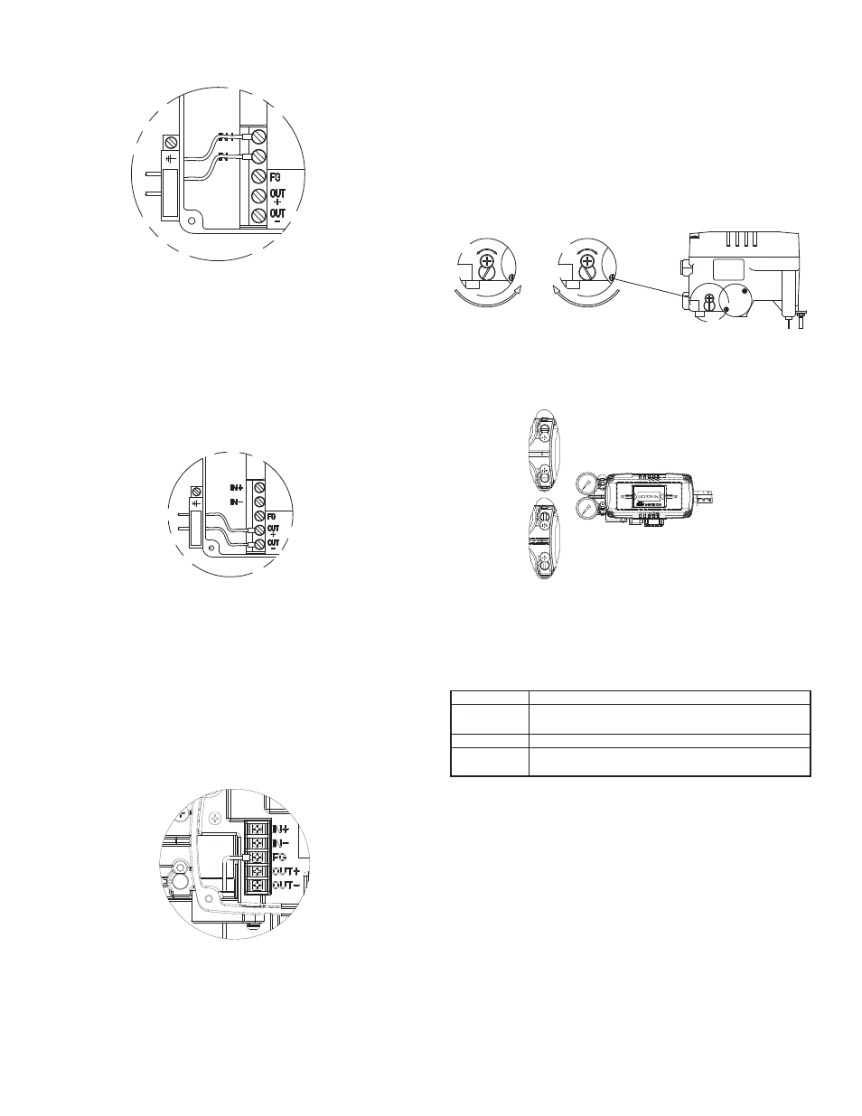
Terminal Connection of Current Input Signal
1. Open cover by loosening the four screws on positioner cover.
2. Loosen locking bolts of terminal plate.
3. Insert a cable through the cable connector in the positioner.
4. Use a ring type cable terminal so that it does not come out.
5. Insert terminal bolts in terminal holes of cable and lock them with (+)
terminal and (–) terminals on the terminal plate. Tighten terminal bolts
with 1.1 lbs-ft (15 kfgcm) torque.
6. Be sure not to change the polarity of terminals.
Terminal Connection of Feedback Signal
1. Open cover by loosening the four screws on the positioner cover.
2. Loosen terminal locking bolts of feedback signal terminals.
3. Insert a cable through the cable connector in the positioner.
4. Use a ring type cable terminal so it does not come out.
5. Insert terminal bolts in terminal holes of cable and lock them with (+)
terminal and (–) terminals on the terminal plate. Tighten terminal
bolts with 1.1 lbs-ft (15 kfgcm) torque.
6. Be sure not to change polarity of terminals.
Inner Terminal Connection for Ground
1. The ground is necessary for the safety of the positioner and system.
2. The ground terminals are inside the terminal in the center of the
terminal plate and outside terminal beside outer cable entry. Use any
ground terminal that is available. Resistance must be less than 100
Ohm.
3. For use with inside ground, open cover by loosening the four screws
of positioner cover.
4. In order to maintain the ground connection, use a ring type ground
cable terminal to prevent it from coming out.
A/M Switch (Auto/Manual switch)
The A/M switch is located on the bottom of the Series 275 positioners.
When set to auto, supply pressure is transmitted to actuator by the
operation of the positioner. When set to manual, supply pressure of
air filter regulator is transmitted to actuator regardless of positioner.
* When A/M switch is set to manual, make sure that supply pressure
range is not exceeded.
1. Make sure supply pressure is within range.
2. Turn switch clockwise and supply pressure of air filter regulator is
transmitted to actuator.
3. Turn switch counter-clockwise to operate positioner manually.
Variable Orifice
Hunting can occur if the actuator volume is too small. In this case, adjust
the variable orifice using a (-) flathead screwdriver. Hunting is prevented
by reducing the flow rate of supply pressure transmitted to actuator.
Auto Calibration and Basic Operations
Warning: Since this makes the valve or actuator move, before auto
calibration, the valve must be separated from entire system.
Buttons Operations
Series 275 positioners perform various functions using four buttons. The
position of the buttons is shown below:
page 4
Terminal connection of input current signal
CABLE
Terminal connection of transmitter
CABLE
Ground terminal connection
A
M
A
M
AUTO
MANUAL
Maximum Open
Minimum Open
Button
Function
Enter to main menu and sub-menus, save adjusted
parameter values, etc.
Return to previous menu
Move to next menu, change parameter values, etc.