3function and specification, 4product profile and outline, Scd1000 – Dwyer SCD User Manual
Page 2: Scd2000
2
3
FUNCTION AND SPECIFICATION
Power Supply
DC24V. Isolated switching power
Voltage Range
Rated voltage: 90% ~ 110%
Power consumption
Rated 24 Vdc, Max. 24 W combined, 3 W + 3 W x no. of SCD2000 (max. 7
connected)
Thermocouple: K, J, T, E, N, R, S, B, L, U, TXK
Platinum RTD: Pt100, JPt100
Sensor Type
Linear DC input: 0 ~ 5V, 0 ~ 10V, 0 ~ 20mA, 4 ~ 20mA, 0 ~ 50mV
Sampling Rate
Analog input: 0.15 sec. Thermocouple or Platinum RTD: 0.4 sec.
Control Method
PID , PID program control, Manual or ON/OFF
Relay output (SPST), Max. load 250VAC, 3A resistive load
Voltage pulse output: DC 12V, Max. output current 40mA
Current output: DC4 ~ 20mA output (Load resistance: Max. 5,00
Ω)
Output Type
Analog voltage output: 0 ~ 10V (Load resistance shall be higher than
1,000
Ω)
Output Function
Control output, Alarm output, or Retransmission output (only for linear
voltage and current output as 1
st
group)
Alarm Function
12 Alarm mode selections
Communication
RS-485 digital communication, 2,400bps ~ 38,400bps.
Communication Protocol
Mod-bus communication protocol, support RTU/ASCII.
Internal Connection
Provide internal connection terminals to transmit 24V power supply and
communication signal.
Vibration Resistance
10 to 55Hz, 10m/s
2
for 10min, each in X, Y and Z directions
Shock Resistance
Max. 300m/ s
2
, 3 times in each 3 axes, 6 directions
Ambient Temperature
0
o
C to + 50
o
C
Storage Temperature
-20
o
C to + 65
o
C
Altitude
2,000m or less
Relative Humidity
35% to 85% RH (non-condensing)
Pollution Degree
Degree 2
4
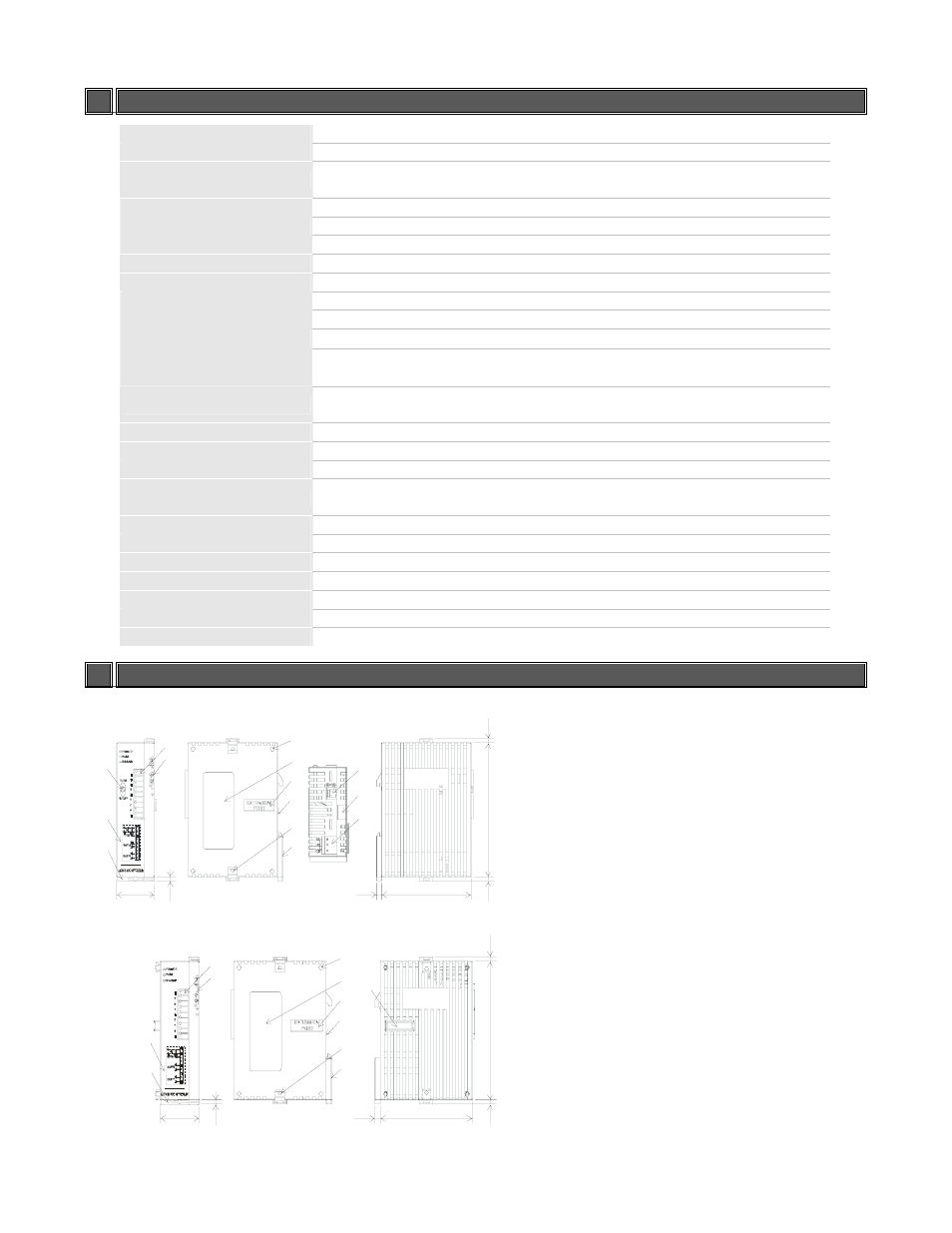
PRODUCT PROFILE AND OUTLINE
SCD1000
1 RUN/STOP switch
2 Wiring and Model name
3 DIN fix
4 I/O terminals
5 LED indicators
6 Extension hole of the extension unit mounting
pins
7 Specification label
8 Extension port
9 Extension clip
10 DIN rail
11 RS-485 communication port
12 Extension clip
90
.0
3.
0
60.0
3.4
25.2
4.
0
3.
0
1
2
3
4
5
6
7
8
9
10
3
11
12
13
13 DC power input
SCD2000
1 Wiring and Model name
2 DIN rail clip
3 I/O terminals
4 LED indicators
5 Extension hole of the extension unit mounting
pins
6 Specification label
7 Extension port
8 Extension clip
9 DIN rail
90
.0
3.
0
60.0
3.4
25. 2
4.
0
3.
0
1
2
3
4
5
6
7
8
9
2
10
10 Extension port