Dwyer SCD User Manual
Page 10
10
RTU Mode:
To Read Instruction
To Read Response
Message
To Write Instruction
To Write Response
Message
Machine address 01H 01H
Machine
address
01H 01H
Machine
address
01H 01H
Machine
address
01H 01H
Instruction 03H 01H
Instruction 03H 01H Instruction 06H 05H
Instruction 06H 05H
10H 08H
10H 08H
10H 08H
Starting address of
reading data
00H 10H
Response data
length (byte)
04H 02H
To write
data
address
01H 10H
To write data
address
01H 10H
00H 00H
01H 17H
03H FFH
03H FFH
To read data length
(word/bit)
02H 09H
Data content 1
F4H 01H
To write
data
content
20H 00H
To write data
content
20H 00H
CRC low byte
C0H BBH
03H
CRC low
byte
DDH 8FH
CRC low byte
DDH 8FH
CRC high byte
CBH A9H
Data content 2
20H
CRC high
byte
E2H 9FH
CRC high byte
E2H 9FH
CRC low byte BBH 77H
CRC high byte 15H 88H
CRC (Cyclical Redundancy Check) program example:
unsigned int reg_crc = 0xffff; i = 0;
while (length--)
{
reg_crc ^= RTUData[i];
i ++;
for (j = 0; j < 8; j++)
{
if (reg_crc & 0x01) reg_crc = (reg_crc >> 1) ^ 0xA001;
else
reg_crc = reg_crc >> 1;
}
}
return (reg_crc);
11
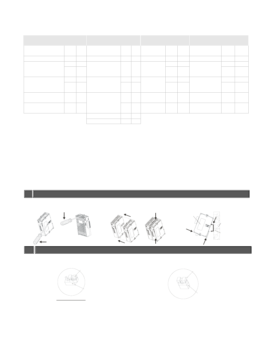
INSTALLATION
SCD series can be extended up to 8 modules and installed by DIN rail mounting.
1
2
SCD unit
Mounting Panel
DIN rail
1
2
3
12
HOW TO SET UP CURRENT INPUT
For normal input
For current input (4 ~ 20mA, 0 ~ 20mA)
JU MP ER
P IN HE A DE R
JP1
DE FA U LT SE TTI NG
J UMP E R
P IN HE A DE R
JP1