Dwyer TE User Manual
Page 2
HeaD LoSS
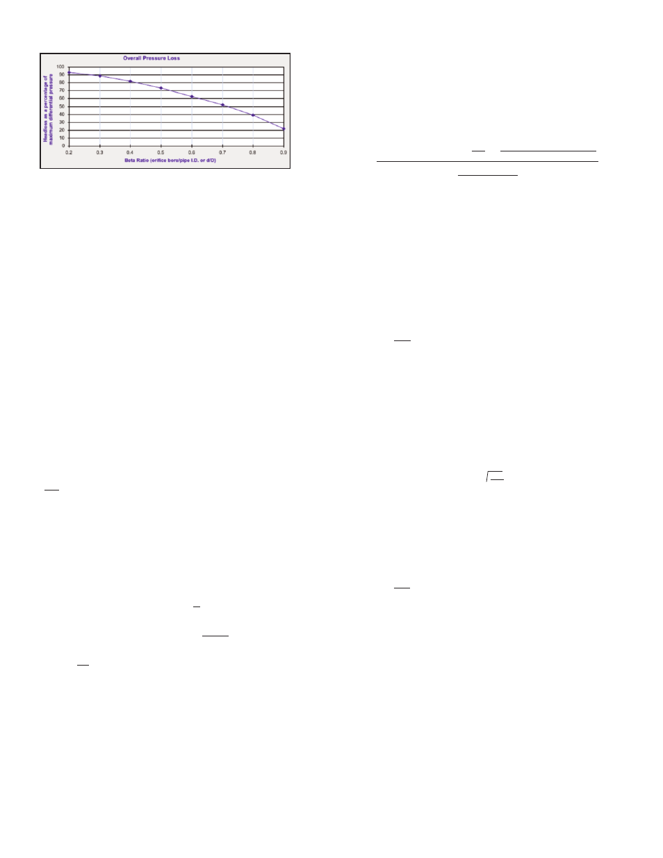
overall pressure Loss across Thin-plate orifices
The curved graph shows pressure loss generated by the Series TE.
For example, a 0.7 Beta Ratio (d/D) would show a loss of 51%.
As a quick check reference, you can use the formula:
Head loss =1-Beta Ratio
2
eg: 1-0.7
2
or 1-0.49 = 51% of the d.p.
Source: ASME Research Report on Fluid Meters
Magnehelic
®
and Capsuhelic
®
gages from Dwyer read pressure drop across the
orifice plates.
For compatible gases a Dwyer
®
Magnehelic
®
gage may be used to read the
differential pressure. Compatible liquids may be used in conjunction with the
Dwyer
®
Capsuhelic
®
gage with brass case.
oVeRaLL pReSSURe LoSS acRoSS SeRIeS Te oRIfIceS
fLoW vs. DIffeRenTIaL pReSSURe ReLaTIonSHIp
(Based on constant inlet temperature and pressure)
[Q
2
/ Q
1
]
2
x h
1
= h
2
Solve for new d.p. based on changes in flow
h
2
/h
1
x Q
1
= Q
2
Solve for new flow based on changes in d.p.
Where:
Q
1
= Existing Flow
Q
2
= New Flow
h
1
= Existing d.p.
h
2
= New d.p.
If the inlet temperature and pressure fluctuate, use the full formula allowing for
input of varying temperature and pressure.
To convert 60°F water flow rates for other fluids:
Pounds per hour (for any fluid) = Q x 63.3 x
γ
L
To convert 60°F water flow rates into flow rates for gases:
Standard cu ft/hour (for any gas) = Q x 63.3 x (
γ
L
)/(
γ
s
)
To convert 60°F water flow rates to GPM for other fluids:
(GPM) / ( SG of fluid)
Explanation of Symbols
Q = 60°F Water Flow Rate in GPM
SG = Specific Gravity
γ
L
= Specific Weight of Line Fluid in lb/ft
3
at line conditions
γ
s
= Specific Weight of Line Fluid in lb/ft
3
at standard conditions (60°F, 14.7 PSIA)
√
√
√
√
aIR anD GaS fLoW - concenTRIc BoRe
ScfM BaSe conDITIonS 14.7 psia & 60°f
Conversion formula used to solve for flow rate based on plotting changes in inlet
pressure, temperature, and/or differential pressure. This formula is designed for
use as a “quick check” reference only as the results may differ from calculation
values due to rounding, combining of variables, and making certain assumptions in
an effort to keep the formula as abbreviated as possible. Equation source Flow
Measurement Engineering Handbook by Richard Miller.
Input new h/w as well as new pressures and/or temperatures using the
formula below:
SCFM =
Where:
5.9816 = physical constant
d = bore in inches
D = Pide Inside Diameter (inches)
K = flow coefficient
Y = expansion factor
h/w= differential pressure (inches w/c)
P
L
= line pressure (psia)
T
L
= line temperature (°F)
T
b
= base temperature (°F)
ß = beta ratio (d/D)
SG = specific gravity at line conditions (air=1.00)
SH = specific heat ratio cp/cv (air=1.4)
R
n
= Reynolds number at max flow in pipe.
K= C x ((1)/( 1-ß
4
))
Y= 1- (.41+.35ß
4
) ((h/w x .0361)/ (P
L
x 1.4))
C= 0.5959 + 0.0312Я
2.1
– 0.1840Я
8
+ 91.71Я
2.5
R
n
-0.75
If Reynolds number (R
n
) is not known, “C” can be estimated as 0.6015.
For convenience other factors can be combined to form constants as the equation
is developed.
2.703 x 14.7 x SG
460 + T
b
5.9816 x (d
2
) x (K) x (Y) x h/w x (2.703 x P
L
x SG)/(460 + T
L
)
√
√
√
WaTeR anD LIQUID fLoW - concenTRIc BoRe
GpM BaSe conDITIonS 14.7 psia & 60°f
GPM =
Where:
44.748 = physical constant
d = bore in inches
K = flow coefficient (formula below)
Y = expansion factor (water normally = 1.00)
Fa = thermal expansion factor (water normally = 1.00)
h/w= differential pressure (inches w/c)
P
L
= density @ line (inlet flowing) conditions
C = discharge coefficient (formula below)
K= C x ((1)/( 1-ß
4
))
Y= 1- (.41+.35ß
4
) ((h/w x .0361)/ (P
L
x 1.4))
C= 0.5959 + 0.0312Я
2.1
– 0.1840Я
8
+ 91.71Я
2.5
R
n
-0.75
If Reynolds number (R
n
) is not known, “C” can be estimated as 0.6015.
For convenience other factors can be combined to form constants as the equation
is developed.
44.748 x (d
2
) x (K) x (Y) x (Fa) x h/w
√
√
P
L
MaInTenance
After final installation of the Series TE Orifice Plate Flow Flowmeter, no routine
maintenance is required. A periodic check of system calibration is suggested. With
the exception of gasket replacement, these devices are not field repairable and
should be returned if repair is needed (field repair should not be attempted and
may void warranty). Be sure to include a brief description of the problem plus any
relevant application notes. Contact customer service to receive a return goods
authorization number before shipping.