Dwyer P72 User Manual
Page 3
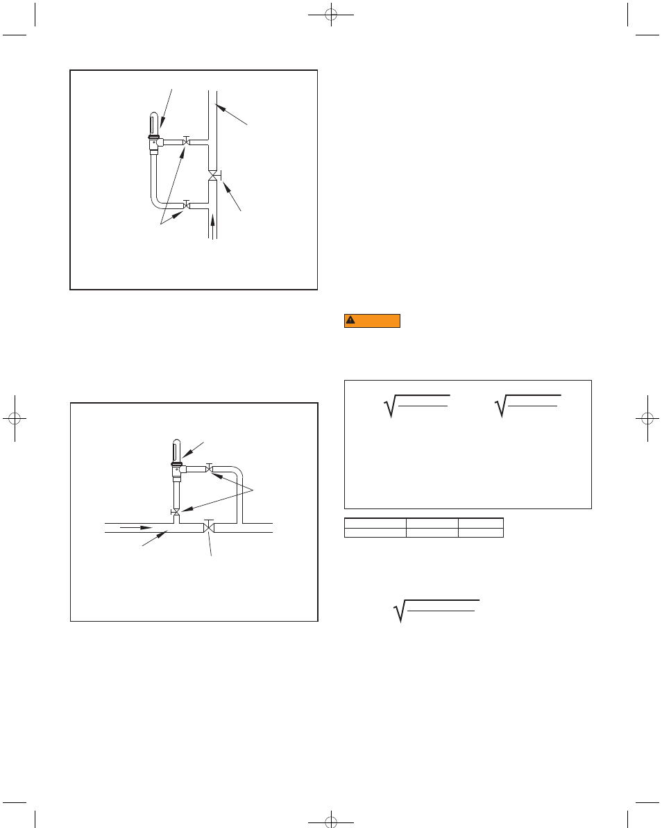
FLOWMETER
MAIN
PROCESS
LINE
BY-PASS
VALVE
FLOW
FIGURE 1: TYPICAL INSTALLATION-
VERTICAL LINE FOR LIQUID, GAS, OR VAPOR
SHUT-OFF
VALVES (2)
FIGURE 2: TYPICAL INSTALLATION-
HORIZONTAL LINE FOR LIQUID, GAS, OR VAPOR
SHUT-OFF
VALVES (2)
FLOWMETER
BY-PASS VALVE
FLOW
MAIN PROCESS LINE
Apply wrenches only on the flats or outer rims of the connection ports. Avoid over-
tightening, and do not use wrenches on other portions of the body or sight tube.
When solvent cementing in the vicinity of a meter with a polysulfone sight
tube, the tube should be removed until the cement dries and fumes clear.
SURGE CHAMBERS & ACCUMULATORS: Flowmeters are more accurate and
less likely to be damaged when the fluid flow is smooth. If the meter must be
installed on a line where reciprocating pumps or compressors causing pulsation
are used, surge chambers or accumulators are strongly suggested to damp the
shock wave.
SIGHT TUBE ROTATION: On P72-A indication models with polysulfone sight
tubes, grasp the tube firmly BY HAND near the body and twist until the scale faces
the desired direction. USE NO TOOLS!
On P72-B flowmeters, the magnet is encapsulated in the top of the float assembly
to seal it from the wetted system.
Figure 1
Figure 2
STARTUP
System flow should be started with the by-pass valve open and meter inlet and
outlet valves closed. After the system is operating, open the meter inlet valve
gradually to equalize internal pressure. Then slowly crack meter outlet valve and
wait for float to stabilize. Finally, slowly open the meter outlet and/or flow regulating
valve all the way and close the system by-pass valve. AVOID SUDDEN SURGES
THAT CAUSE THE METER FLOAT TO SLAM INTO THE TOP OF THE SIGHT
TUBE! Although not essential, the meter sight tube should be filled to a level above
the float on liquid systems. The snorkel tube (present in most standard models)
allows escape of entrapped gases except for a small pocket in the upper end which
helps cushion hydraulic shock. To assure proper filling and to flush any foreign
particles from the meter, operate the system at full flow briefly at startup.
READING FLOW
On transparent sight tube models, read flow directly from the scale as the number
nearest the top edge of the float indicator disk. For magnetically-linked models,
flow is read at the center of the ball indicator.
COMPENSATING FOR SYSTEM CHANGES
To find the correct flow reading for a system whose fluid conditions vary from those
for which the meter is scaled, use the conversion data below. The most practical
method of applying the formulae is to calculate a conversion factor for the new
system conditions, multiplying the scale reading by that factor. In the problems
below, ˝Qs˝ has been assigned a value of ˝1˝ to determine the conversion factor.
(The factory can provide special scales at additional cost for other fluids and/or
units.)
DO NOT OPERATE THE FLOWMETER ON A SYSTEM
EXCEEDING THE OPERATING LIMITS OF THE UNIT. WHEN CHANGING
OPERATING CONDITIONS, MAKE SURE THAT THE NEW SYSTEM
CONDITIONS ARE WITHIN THE FLOWMETER OPERATING LIMITS, AND ALL
WETTED MATERIALS ARE COMPATIBLE WITH THE FLUID.
CORRECTING READINGS FOR NEW LIQUID CONDITIONS
Qa = Qs
or Qa = Qs
Where:
Qa = Actual flow, GPM (or same units as scale).
Qs = Meter reading from scale, (scale units).
ps =
Specific gravity of calibration liquid related to water in
std. atmosphere at 70°F. being 1.00.
pa =
Specific gravity of metered liquid, same base.
ds =
Density of calibration liquid, lbs/ft3.
da =
Density of metered liquid, lbs/ft3.
pf =
Specific gravity of meter float.
df =
Density of the meter float per table.
ps (pf - pa)
pa (pf - ps)
ds (df - da)
da (df - ds)
Material
P72-A/P72-B
pf
VARIES*
df
VARIES*
*Average for these floats is f = 3.50, df = 217.8.
EXAMPLE: Using a standard brass meter scaled for water (s = 1.00), what is the
conversation factor for an oil with a specific gravity of 0.85?
1.00 (8.30 - 0.85)
0.85 (8.30 - 1.00)
Qa = 1.00 x
= 1.096
WARNING
F-P72:TEMPLATE 8/19/10 12:11 PM Page 3