Dwyer P72 User Manual
Page 2
INSTALLATION
PREPARATION: Series P72 Flowmeters are ready to install as-is, although the
sight tube may need repositioning so the scale is visible after installation. First,
remove the protective caps from the connection ports. ALSO, REMOVE THE
PLASTIC SHIPPING TUBING ABOVE THE INLET CAP IN THE METER CORE
TUBE! Check that the float moves freely within the core tube, and that no packing
materials are in the meter.
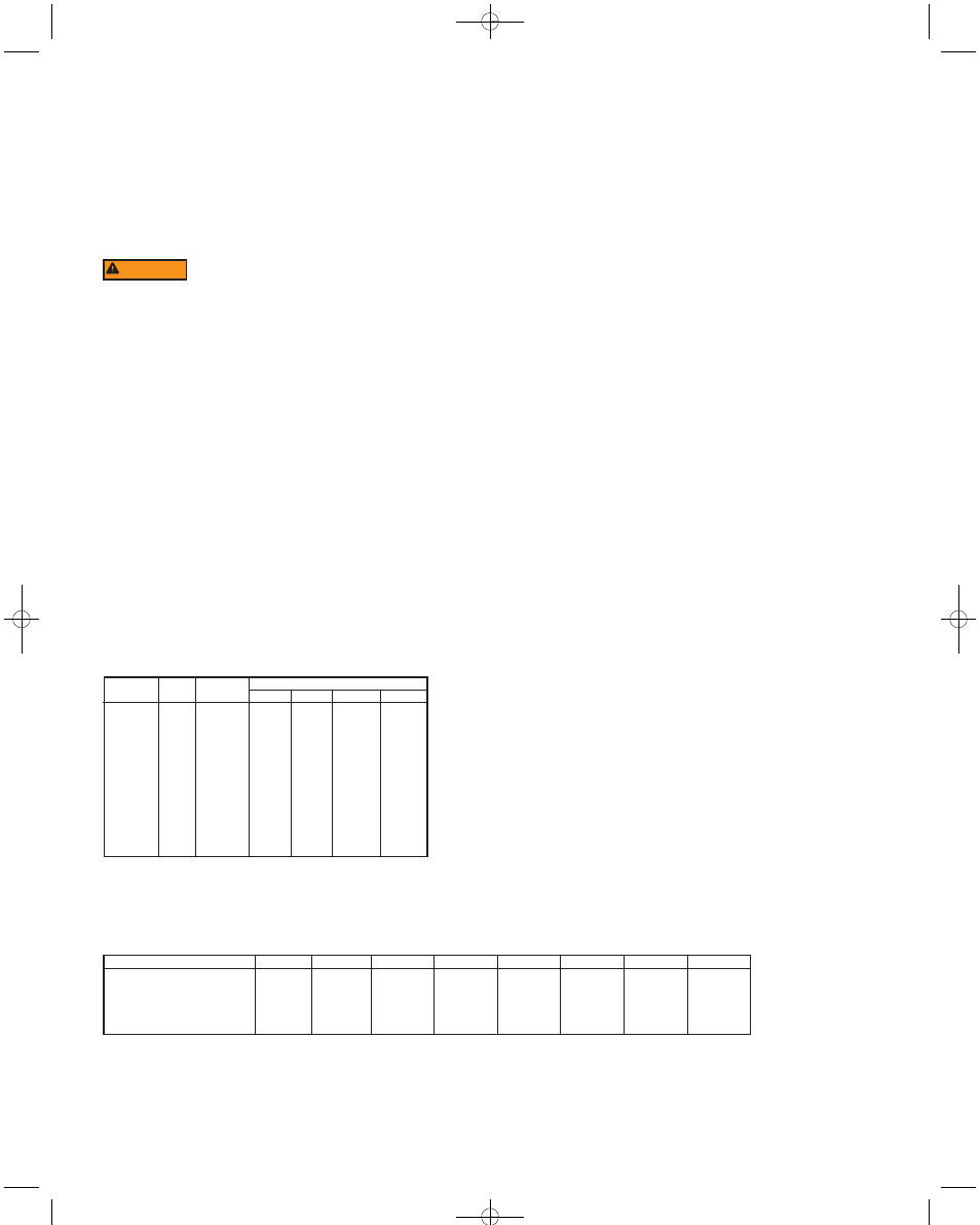
MAXIMUM FLOWS (WITHOUT EFFECTING ACCURACY)
FOR UNDERSIZED PIPES CONNECTED DIRECTLY TO FLOWMETER INLETS
PIPE NPS
1/4
3/8
1/2
3/4
1
1-1/4
1-1/2
2
2-1/2
3
4
6
DATA
(ID)
2
0.132
0.243
0.387
0.679
1.100
1.904
2.592
4.272
6.096
9.413
16.209
36.784
MAX. *
GPM LIQ.
1.72
2.98
4.74
8.31
13.47
23.32
31.74
52.29
74.56
115.2
198.4
450.0
ATMOS
0.864
1.59
2.53
4.44
7.20
12.5
17.0
28.0
39.9
61.6
106
241
50 PSIG
3.80
7.00
11.1
19.5
31.7
58.8
74.6
123
176
271
467
1059
100 PSIG
6.74
12.4
19.8
34.7
56.1
97.2
132
218
311
480
827
1878
MAX. SCFM AIR @ †
200 PSIG
12.6
23.2
37.2
64.9
105
182
248
408
582
804
1549
3514
* Data per Cameron Hydraulic Data. Based on 5 FPS max. liquid velocity having no effect on Series P72 flowmeters
accuracy if the inlet pipe is smaller than the meter connections.
† SCFM = 0.445 x (psig + 14.7) x (ID)2. Based on 20 FPS max. air velocity having no effect on Series P72 flowmeters
accuracy if the inlet pipe is smaller than the meter connections.
The Series P72 Flowmeters are heavy bodied meters for corrosives, gases, and
high purity fluids. These meters are designed specifically for demanding
applications. They are economically priced meters ideal for caustic solutions as well
as liquid chlorine, sodium hypochlorite and chlorine gas. The Series P72 Flowmeters
are suited for water treatment facilities that deal with these aggressive types of
gases and fluids. The P72-A is comprised of P72 and polysulfone, while the P72-B
has all P72 wetted components for maximum corrosion resistance. Units have a full-
scale accuracy of ±2% and can be disassembled quickly without the meter being
removed from the pipeline for easy cleaning. The Series P72 Flowmeters are
available with standard 3/4˝, 1-1/2˝, 3˝, and 4˝ flange connections. Optional NPT
connections are also available.
SAFETY PRECAUTIONS
Personnel safety should be considered before pressurizing and operating the
system. There are numerous possibilities for error in system operation and
maintenance as well as component installation. Because human eyes must
necessarily come into close proximity with the flowmeter to read it, it is
recommended that safety shielding be used with the meter along with safety
glasses. Another protective measure is to use a sheet of transparent, high-impact
material in a broad area in front of the meter. If hazardous, toxic, or flammable
fluids are being metered, recommended safeguards should include methods to
protect personnel from splash or rebound. A method of quick, safe removal of
dangerous fluids should also be included.
RECOMMENDED PIPING: Series P72 Flowmeters generally have no special
straight run or other piping requirements. Inlet piping should be the same size as
the meter connection. Some effect on meter accuracy may occur at high flow
velocities if inlet piping guidelines are violated. Please refer to the table below.
When installing on different size pipe, use standard pipe adapters and come into
the meter inlet with a nipple 8 diameters long of the same size for greatest
accuracy. Control valves should be mounted on the outlet side of the meter. The
use of a three valve manifold around the meter is suggested (per Figures 1 & 2) as
it allows uninterrupted process flow while the meter is being cleaned.
SPECIFICATIONS
Service: Compatible gases or liquids.
Wetted Materials:
P72-A: P72, polysulfone;
P72-B: P72.
Temperature Limits: See operating limits.
Pressure Limits: See operating limits.
Accuracy: ±2% of full scale.
Repeatability: ±1/2% of indicated flow rate.
Process Connections: 3/4˝, 1-1/2˝, 3˝ and 4˝ flange connection with optional
NPT connection available.
Weight: 3 lb (1.4 kg) for 3/4˝, 9 lb (4.1 kg) for 1-1/2˝, 14 lb (6.4 kg) for 3˝, and 18
lb (8.2 kg) for 4˝.
Body Size and Description
3/4˝ P72-NPT connection
1-1/2˝ P72-NPT connection
3/4˝ P72-Flange connection
1-1/2˝ P72-Flange connection
3˝ and 4˝ P72-Flange connection
70°F (21°C)
270 (19)
180 (12)
150 (10)
150 (10)
150 (10)
80°F (26°C)
270 (19)
180 (12)
150 (10)
150 (10)
150 (10)
100°F (37°C)
250 (17)
170 (11)
150 (10)
150 (10)
150 (10)
120°F (48°C)
200 (10)
145 (10)
135 (9)
135 (9)
135 (9)
140°F (60°C)
150 (10)
115 (8)
110 (8)
110 (8)
110 (8)
160°F (71°C)
130 (9)
75 (5)
90 (6)
90 (6)
90 (6)
180°F (82°C)
80 (6)
50 (3)
70 (5)
70 (5)
70 (5)
210°F (98°C)
50 (3)
30 (2)
40 (2)
40 (2)
40 (2)
OPERATING LIMITS FOR SERIES P72 FLOWMETERS
Maximum Non-Shock Working Pressure, PSIG @ °F (bar @ °C)
WARNING
F-P72:TEMPLATE 8/19/10 12:11 PM Page 2