Tdc_iom 4, Specifications, Step two – Dwyer TDC User Manual
Page 2: Dimensions, Make a fail-safe system, Tdc1 faceplate approval label, Tdc2 faceplate, Part number information, Functional diagram
SPECIFICATIONS
Step Two
Supply voltage:
120 / 240 VAC, 50 - 60 Hz.
Consumption:
5 Watt
Sensor supply:
13.5 VDC @ 100 mA
Relay type:
TDC1: (1) SPDT
TDC2: (1) SPDT, (1) Latched SPDT
Relay load:
250 VAC, 10A, 1/2 hp.
Relay mode:
Selectable, NO or NC
Time delay:
0 to 60 seconds
LED indication:
Sensor, relay & power status
Fail safety:
Power fail-safe
Temperature range:
F: -40 to 158
C: -40 to 70
Enclosure rating:
Panel or 35 mm DIN Rail
(EN 50 022)
Enclosure material:
Polypropylene (U.L. 94 VO)
Certificate number:
LR 79326-3 (CSA/NRTL)
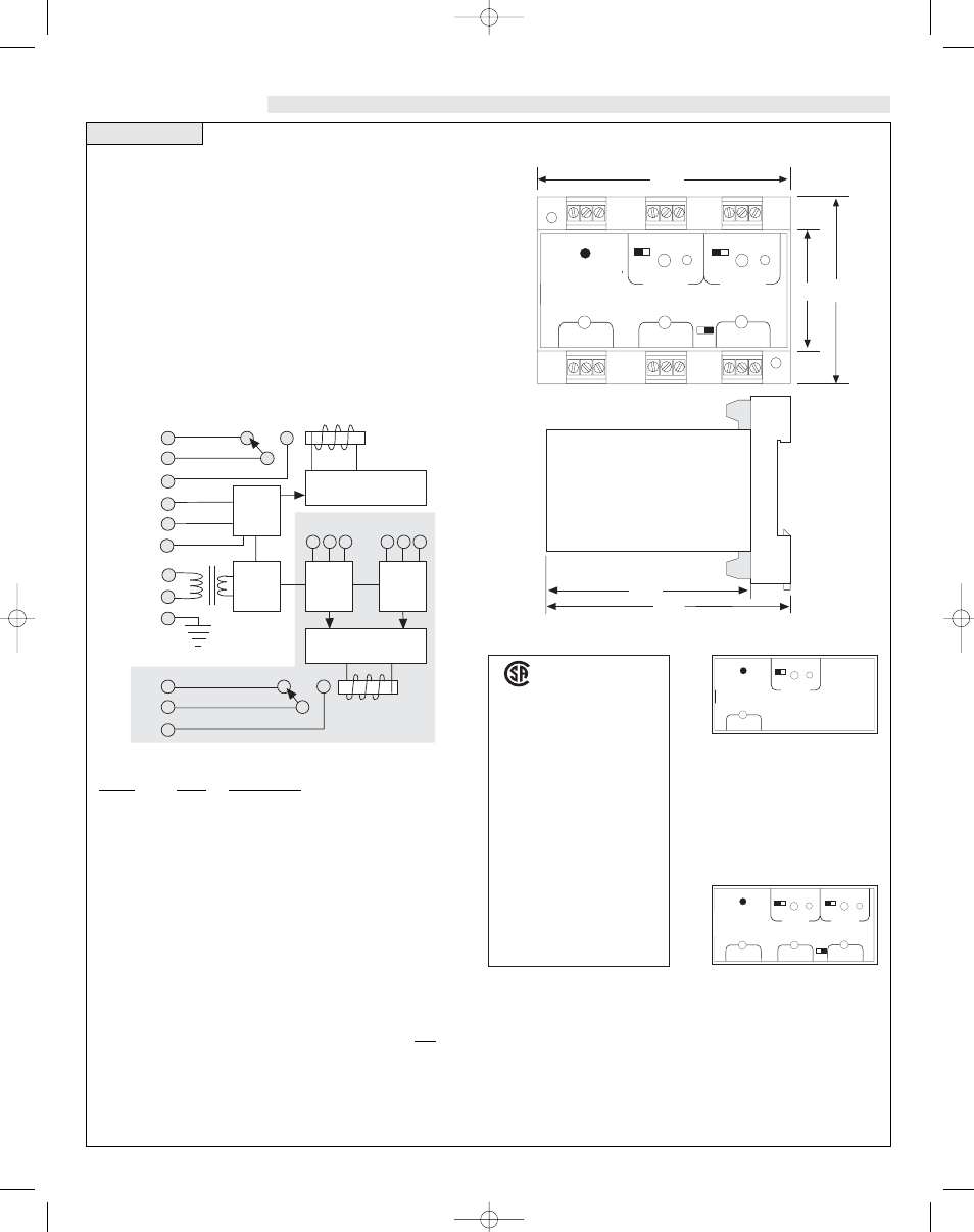
Dimensions
2.7"
1.8"
R E L A Y 1
R E L A Y 2
P O W E R
I N V E R T
I N V E R T
D E L AY
D E L AY
ONOFF
LATCH
I N P U T 1
I N P U T 2 A
I N P U T 2 B
+
—
+
—
3.9"
3.6"
3.1"
Make a Fail-Safe System:
Design a fail-safe system that accommodates the possibility of relay or
power failure. If power is cut off to the controller, it will de-energize the
relay. Make sure that the de-energized state of the relay is the safe state in
your process. For example, if controller power is lost, a pump will turn off
if it is connected to the Normally Open side of the relay.
While the internal relay is reliable, over the course of time relay failure is
possible in two modes: under a heavy load the contacts may be “welded”
or stuck into the energized position, or corrosion may build up on a
contact so that it will not complete the circuit when it should. In critical
applications, redundant backup systems and alarms must be used in
addition to the primary system. Such backup systems should use different
sensor technologies where possible.
While this manual offers some examples and suggestions to help explain
the operation of Dwyer products, such examples are for information only
and are not intended as a complete guide to installing any specific system.
LR79326 -3
®
Power Supply
Refer to the instruction
manual for installation
instructions.
120/240 VAC, 50 - 60 Hz
5 Watt
250 VAC, 10 A, 1/2 Hp
Maximum Relay Rating
NRTL-C
TDC1 Faceplate
Approval Label
+
R E L AY 1
P O W E R
I N V E R
T
-
-
D E L AY
I N P U T 1
+
R E L AY 1
R E L AY 2
P O W E R
I N V E R
T
I N V E R
T
D E L AY
-
-
+
-
-
D E L AY
ONOFF
LATCH
I N P U T 1
I N P U T 2 A
I N P U T 2 B
TDC2 Faceplate
Power
Supply
Latch / Invert Logic
Time Delay
AC
AC
GND
Sensor
Input
A*
Sensor
Input
B*
Relay
("Relay 2" in LC82)
Relay
("Relay 1"
in LC82)
NC
C
NO
Sensor
Input
1
Latch / Invert Logic
Time Delay
NC
C
NO
(+)
(-)
S
+ - S
+ - S
Part Number Information:
Part #
Mat'l
Description
TDC1
PP
Flow/No-Flow Controller
TDC2
PP
Dual Flow/No-Flow Controller
Functional Diagram
TDC 1/4/05 4:10 PM Page 4