Dwyer PFT User Manual
Page 2
Connecting Sensor to Fitting
It is recommended to use a weld-on or saddle female fitting with 1-1/2˝ or 2˝ NPT
connection depending on sensor model. Use proper pipe sealant on sensor
threads. When threading the sensor into the fitting use the wrench flats on the
bottom of the housing to prevent damage to the sensor.
The sensor must be aligned with the direction of flow. On the side of the sensor
body is a hole for the included alignment rod. Insert the supplied alignment rod into
the alignment hole (Do not turn the alignment rod to loosen the screw in the
alignment hole). When threading the sensor into the fitting make sure that when the
rod is inserted into the hole it is pointing downstream in the direction of flow. Try
to line it up as best as can be done. If the sensor is off slightly once threaded into
the fitting then the sensor can be rotated in the housing during final installation but
adjustment is only ±60°.
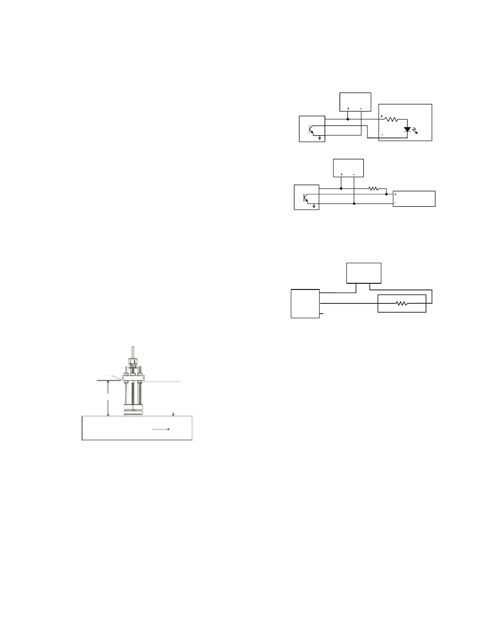
Sensor Height
The sensor must be installed so that the impeller shaft is located 10% inside the
pipe ID. To install properly the sensor install height, “H” shown in Figure 2, must be
figured and used. Table 2 in this instruction manual has “H” dimensions for
standard pipe materials and sizes.
If your application pipe is not listed in Table 2 it will need to be calculated with the
following procedure:
1. Using a ruler measure the pipe ID and the pipe wall thickness.
Pipe Wall Thickness:_______ Pipe ID:_______
2. Use the following equation to figure “H”:
H = 5.85 – Pipe Wall Thickness – (0.10 x Pipe ID)
H = _____
Once “H” is known from the chart or from the equation adjust the sensor so that “H”
is the distance from the bottom of the flange to the top of the pipe. The insertion
height of the sensor is adjustable by loosening the top and bottom nuts holding the
flange and then moving the sensor by the flange up or down as needed.
Final Sensor Alignment
The sensor must be aligned with the direction of flow. Insert the supplied alignment
rod into the hole in the side of the sensor. The hole should be roughly in line based
on installing the sensor into the fitting earlier. To make final adjustments loosen the
three 3/32˝ set screws around the flange, the supplied alignment rod can be used
with these screws. With the alignment rod in the alignment hole the sensor can now
be rotated ±60° (Do not turn the alignment rod to loosen the screw in the alignment
hole). Once final alignment is made tighten the screws in the flange and tighten the
height adjustment nuts.
CALIBRATION TABLES
The PFT uses K factors for calibration. See Table 2 in this instruction manual for K
factors based on pipe type and size used in the application.
For 4-20 mA output version use the following equation to convert to flow rate.
q = (I-4) x K
Nomenclature:
q = Liquid volumetric flow rate
I = Transmitted mA output
K = K - factor. If use GPM/mA then q will be in U.S. GPM. If use LPM/mA then q
will be in LPM.
DIRECTION OF FLOW
PIPE
H
ALIGNMENT ROD
BOTTOM OF
SENSOR FLANGE
ELECTRICAL CONNECTION
Pulse Output Wiring
The PFT has a NPN open collector output. The output rating is 60V @ 50 mA
maximum. Typical wiring to a PLC or counter is shown in Figure 3 and Figure 4.
When wiring to a counter, select the Power Supply voltage and Dropping Resistor
according to the counter’s instructions and make sure the Power Supply is within
the 10-35 VDC specification of the PFT.
To insure noise immunity, wire the shield conductor to an earth ground.
The PFT can also be wired in a two-wire pulse output, 600 µA / 40 mA configuration
with the red and black leads only to replace competitor units. Unit needs 600 µA of
power and produces 40 mA 2.5 ms pulses. Consult factory for details.
4-20 mA Output Wiring
AGENCY APPROVALS AND TEST STANDARDS
CE: CENELEC EN 55011: 2006
CENELEC EN 61326-1: 2006
IEC 61000-4-2: 2008
IEC 61000-4-3: 2006
IEC 61000-4-4: 2004
IEC 61000-4-5: 2005
IEC 61000-4-6: 2006
CENELEC EN 55022: 2006
2004/108/EC EMC DIRECTIVE
Note: For 4-20 mA output models only under the 10 V/M RF field as specified in
IEC 61000-4.3, linearity may be as high as ±3.7%. Under normal ambient
conditions linearity is ±1%.
MAINTENANCE & REPAIR
Inspect and clean wetted parts at regular intervals. Disassembly or modifications
made by the user will void the warranty and could impair the continued safety of
the product. If repair is required obtain a Return Goods Authorization (RGA)
number and send the unit, freight prepaid, to the address below. Please include a
detailed description of the problem and conditions under which the problem was
encountered.
Dwyer Instruments, Inc.
Attn: Repair Department
102 Indiana Hwy 212
Michigan City, IN 46360
PARTS
P-PFT-KITA: Contains impeller, PTFE bearings, cage bearing set screws, tungsten
carbide shaft
P-PFT-KITB: Contains impeller, PTFE bearings, cage bearing set screws, 316SS
shaft
Figure 2: Sensor Install Height
PWR SUPPLY
24 VDC
TYPICAL PLC HIGH SPEED
COUNTER INPUT
PFT
RED
+PWR
OUT
-COM
WHITE
BLACK
Figure 3
PWR SUPPLY
RED
WHITE
BLACK
PULL UP
RESISTOR
PFT
+PWR
OUT
COUNTER WITH
LOGIC LEVEL INPUT
-COM
Figure 4
Figure 5
+
+
+
-
-
-
PWR SUPPLY
RED
WHITE - NO CONNECTION
4-20 mA
LOOP
BLACK
RECEIVER