Dwyer 641 User Manual
Page 2
NOTE: Where conduit connections are not made, a 1/2˝
NPT cable seal should be used to prevent contaminants
from entering the case. Where conduit connections are
made, make sure that any possible condensation within the
conduit will not flow into the transmitter housing.
ELECTRICAL CONNECTION
The Series 641 AVT has been designed for easy and flexi-
ble connection to power and loop receivers. Electrical con-
nection is made inside the body of the device with a “Euro”
style terminal block. The device features a current loop that
is fully isolated from the power source. The current loop has
an internal 24V isolated supply so no external loop power is
required. With full isolation, loop grounding is not a concern.
The input power requirements are also very flexible. The
device may be powered from either an AC or DC power
source.
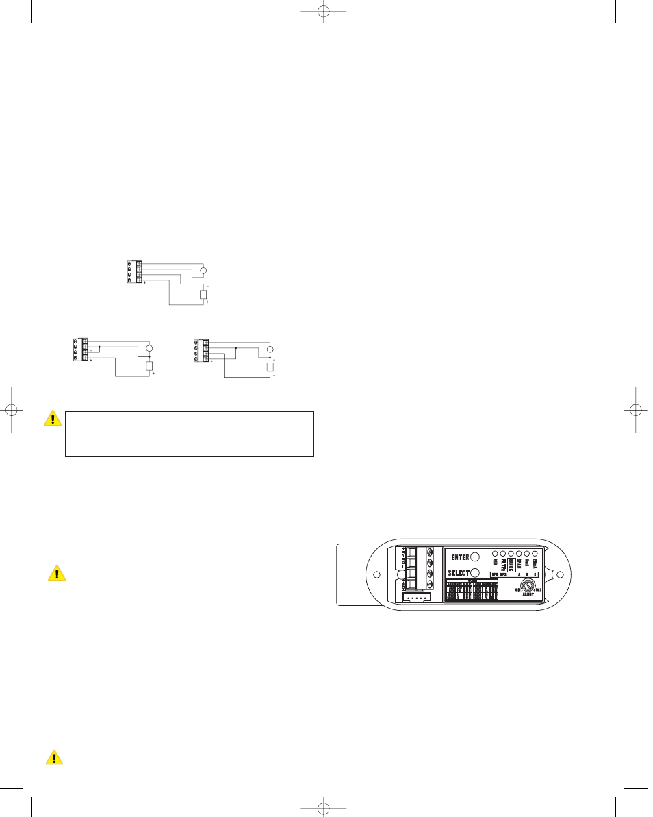
3 or 4-Wire Connection
CAUTION: Do not exceed the specified supply voltage rat-
ing. Permanent damage not covered by the warranty may
result. Do not use an external power source on the current
loop connection.
Receiver-Transmitter Connection — The Series 641
AVT is designed as a three or four wire 4-20 ma device. The
current loop output is isolated from the power supply input
and provides an internal 24-volt loop supply. With a DC
power supply, a three or four-wire connection may be used.
Do not use a three-wire connection with an AC power
source. In a three-wire connection either power supply wire
may be used as the common. The total loop resistance
should not exceed 600 Ohms.
CAUTION: Do not use a receiver with an internal power
supply or use an external supply in the current loop. The
current loop is powered from within the Series 641 AVT.
Connecting an external supply to the current loop may
destroy the transmitter. Using an external supply voids the
warranty.
Power Supply Connection — The power supply may be
either AC or DC. The DC power may be from 12 to 35 Volts.
The power connection is not polarity sensitive so the posi-
tive and negative connections may be made to either power
terminal. The AC connection may be from 10 to 16 VAC
RMS. Do not exceed 20 VAC. When selecting a transformer
please note that the specified output for transformers is at
some specified current. With a load current less than the
specified current transformer output may be significantly
higher than the specified voltage. Transformers with sec-
ondary voltages of 10 to 16 VAC are recommended.
CAUTION: Do not use transformers with a secondary volt-
age rating greater than 16 VAC RMS.
Wire Type and Length — The wire selection for an instal-
lation is often overlooked or neglected and may contribute
to improper or even intermittent operation. In all cases
ensure that the connection meets all applicable national
and local electrical codes. Although the 4-20 mA current
loop systems are relatively immune to wire or wiring related
problems, selection of the wire for some installations will be
an important factor in ensuring satisfactory system opera-
tion. Twisted conductors will usually be immune to most
stray electric and magnetic fields and to some extent elec-
tromagnetic fields, such as interference from RF transmit-
ters. With twisted pair wiring the current loop and the
power connections should be separate pairs. Avoid using
flat or ribbon cable that has no regular conductor twist.
Where interference is possible, it is recommended that
shielded wire be used. The shield must not be used as one
of the conductors and should be connected to ground at
only one end, generally at the power supply. Similarly, if the
installation uses conduit, the conduit should be connected
to protective ground as specified by the applicable code
and the signal wiring must not be connected to the conduit
at more than one point or as specified by the code.
The maximum length of wire connecting the transmitter
and receiver is a function of the wire resistance and receiv-
er resistance. The total loop resistance must not exceed
600 Ohms, including the receiver resistance and wire resis-
tance. The power supply connection must be designed so
that the worst case voltage drop due to wire resistance will
not cause the power supply voltage at the transmitter to
drop below the specified value. Provided the power supply
voltage is maintained within the specified voltage range, the
Series 641 AVT is not affected by variations in power sup-
ply voltage.
TRANSMITTER SETUP
The Series 641 AVT has been designed for easy setup. It
has five configuration parameters that may be adjusted by
the user. These parameters are Output Filter, Range (In
English or Metric), span, 4 mA set-point and 20 mA set-
point. All of these may be adjusted at any time in the field.
These adjustments may also be easily returned to factory
default.
A set of controls and indicators are provided within the unit
consisting of the select button, enter button, adjustment
control, and six LED indicators. When operating normally,
only the RUN LED indicator will be illuminated. During the
setup operation the LED indicators will indicate the para-
meter selected, when it is being adjusted, and status of the
adjustment process. If the unit is left in the setup mode for
several minutes without any activity it will return to the
normal operating mode.
Interior Label Diagram
POWER SUPPLY
AC OR DC
RECEIVER
4-WIRE
3-WIRE
RECEIVER NEGATIVE
COMMON
RECEIVER
DC SUPPLY
ONLY
(EITHER
POLARITY)
3-WIRE
RECEIVER POSITIVE
COMMON
RECEIVER
DC SUPPLY
ONLY
(EITHER
POLARITY)
Page 2
641-CE bulletin 11/9/04 3:49 PM Page 2