Dwyer IS626 User Manual
Page 2
CAUTION: Do not exceed specified supply voltage
ratings. Permanent damage not covered by war-
ranty will result. This device is not designed for 120
or 240 volt AC operation. Use only on 10 to 28
VDC.
INSTALLATION
1. Location: Select a location where the temperature of the transducer will
be between 0 and 176°F (-18 to 80°C). Distance from the receiver is lim-
ited only by total loop resistance. The tubing or piping supplying pressure
to the unit can be practically any length required but long lengths will in-
crease response time slightly.
2. Position: The transducer is not position sensitive. However all stan-
dard models are originally calibrated with the unit in a position with the
pressure connection downward. Although they can be used at other an -
gles, for best accuracy it is recommended that units be installed in the po-
sition calibrated at the factory.
3. Pressure Connection: Use a small amount of plumber’s tape or other
suitable sealants to prevent leaks. Be sure the pressure passage inside
the port is not blocked.
4. Electrical Connections
Wire Length - The maximum length of wire connecting the transducer
and receiver is a function of wire size and receiver resistance. Wiring
should not contribute more than 10% of the receiver resistance to total
loop resistance. For extremely long runs (over 1000 feet), choose re-
ceivers with higher resistance to minimize the size and cost of connecting
leads. Where wiring length is under 100 feet, wire as small as 22 AWG can
be used.
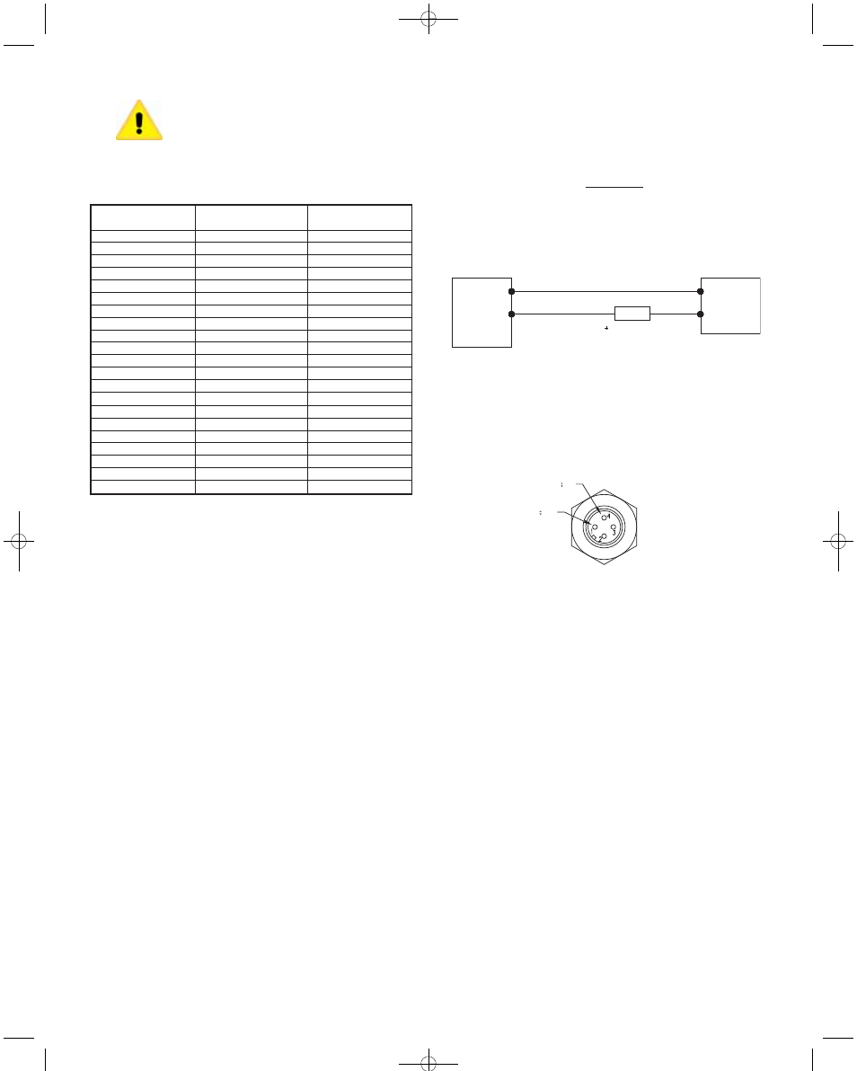
5. Wiring
An external power supply delivering 10-28 VDC with minimum current ca-
pability of 40 mA DC (per transducer) is required to power the control loop.
See Fig. A for connection of the power supply, transducer and receiver.
The range of appropriate receiver load resistance (RL) for the DC power
supply voltage available is expressed by the formula:
Shielded cable is recommended for control loop wiring.
When using cable version IS626, black wire is negative (-) and red wire
is positive (+). When using 4-pin M-12 connector models, wire to pins as
shown below in Fig. B.
Pressure
Range (psig)
30˝ Hg-0
30˝ Hg-0-15
30˝ Hg-0-30
30˝ Hg-0-45
30˝ Hg-0-60
30˝ Hg-0-100
0-5
0-15
0-30
0-50
0-100
0-150
0-200
0-300
0-500
0-1000
0-1500
0-2000
0-3000
0-5000
0-8000
Maximum
Pressure (psig)
30
30
60
100
200
200
10
30
60
100
200
300
400
600
1000
2000
3000
4000
6000
7500
10000
Over
Pressure (psig)
150
150
300
300
500
500
50
150
300
300
500
750
1000
1500
2500
5000
5000
5000
7500
10000
12000
Pressure Range Table
POWER
SUPPLY
10-28 VDC
-
RECEIVER
BLACK
RED
PRESSURE
TRANSDUCER
mA
Fig. A
TERMINAL 4 (-)
TERMINAL 1 (+)
Fig. B
Male-12 Connector
R
L max
=
Vps - 12.3V
20 mA
Project3:Layout 3 12/7/09 11:21 AM Page 2