Dwyer DL7 User Manual
Page 6
Label
If working with more than one logger, label each, identifying the
task and location before you distribute them throughout a build-
ing or system. To do this, simply use shipping tags. Later, when
you retrieve them to graph their data, you will know what each
graph refers to.
Mounting
Use the magnetic backing to conveniently mount the logger on
metal surfaces like ductwork or electrical control cabinets. If
concerned about theft, make sure to lock the logger to a perma-
nent fixture using the special locking tab.
Special mounting methods (using Velcro® fasteners) to secure
the loggers to other surfaces may be used. NOTE: Do not rely
on the logger’s magnetic strip for secure mounting if the surface
is uneven, unstable, or above 150°F (65°C).
Keep Track
Be sur to keep record of the locations of each logger. This will
save time in looking for them when the data-gathering is com-
pleted. Also, keep track of when the loggers were put into ser-
vice. This will help when producing graphs.
Retrieval
After sufficient time has passed to obtain a representative profile
of data, retrieve the logger and bring it back immediately for
analysis. Make sure the logger has a label so it can be properly
identified and differentiated.
Analysis
To analyze the logger, you must first transfer a copy of its data
into your computer. To do this, plug the logger into the
Trendreader interface cable and choose Logger, Communicate,
Backup. After describing the information to the computer, the
data is automatically copied to disk, time and date stamped, and
converted into the appropriate measurement units. A portion or
the entire data set can be copied.
Each file will initially have the same descriptive title, but you can
use Files, Revise Logger to alter these accordingly. To view
graphs, choose Draw, New and select the appropriate file. A
detailed description of all software functions can be found in the
Trendreader Reference Guide.
OPERATING A LOGGER NETWORK
The Series DL7 Dataloggers can be networked to enhance the
monitoring and backup capabilities. Use model IC-200 Interface
Module to connect as many as 8 loggers to your computer
simultaneously. The IC-200 Module will allow backup of a 8 log-
gers, one after the other, with one command. Realtime data
from up to 64 channels (8 loggers with 8 channels) can be dis-
played on a single screen.
Connecting an IC-200 to the Computer
1. Connect the serial port extension cable’s female end to the
computer’s 25-pin serial port. Use the 9-pin connector if the
computer has a 9-pin port).
2. Connect the cable’s other end to the IC-200 connection
maked “PC”.
3. Connect the power supply adapter to the other end of the IC-
200 (the end marked “modem”).
4. Connect the 6VDC power supply to the adapter.
Connecting an IC-200 to a Modem at a Remote site
1. Connect the serial port extension cable to the modem.
2. Connect the cable’s other end to the IC-200 connection
marked “modem”.
3. Connect the gender changer to the other end of the IC-200
(marked “PC”).
4. Connect the power supply adapter to the gender changer.
5. Connect the 6VDC power supply to the adapter.
NOTE: The cable length between the IC-200 and the computer
or modem can be extended. Maximum length should be 500
feet (150 m). Use 22-gauge stranded wire, with two conductors
and a shield.
Identifying Loggers on a Network
Before you can contact a networke group of loggers at a site for
the first time, you must name the site and list serial numbers so
they can be identified.
1 From the Communicate menu in the main Trendreader win-
dow, choose SR+ Network so that a check mark exists in front
of it.
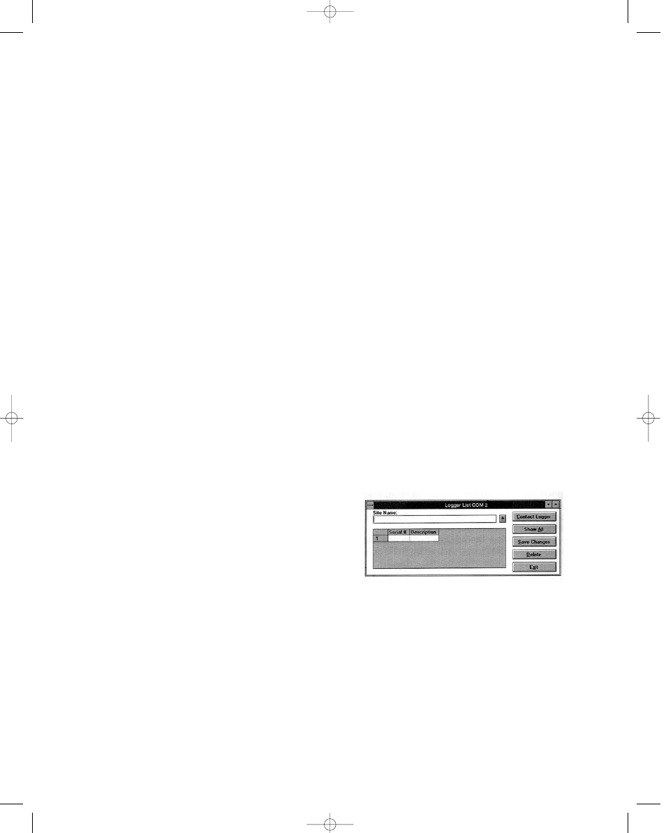
2. Choose the COM port that the loggers are connected to. the
Logger List dialog box will appear. Site name and logger serial
numbers will be entered in this dialog box. See figure 3 below.
FIGURE 3
Bulletin E-90-DL7 6/22/05 3:52 PM Page 6