Dwyer RSM User Manual
Page 5
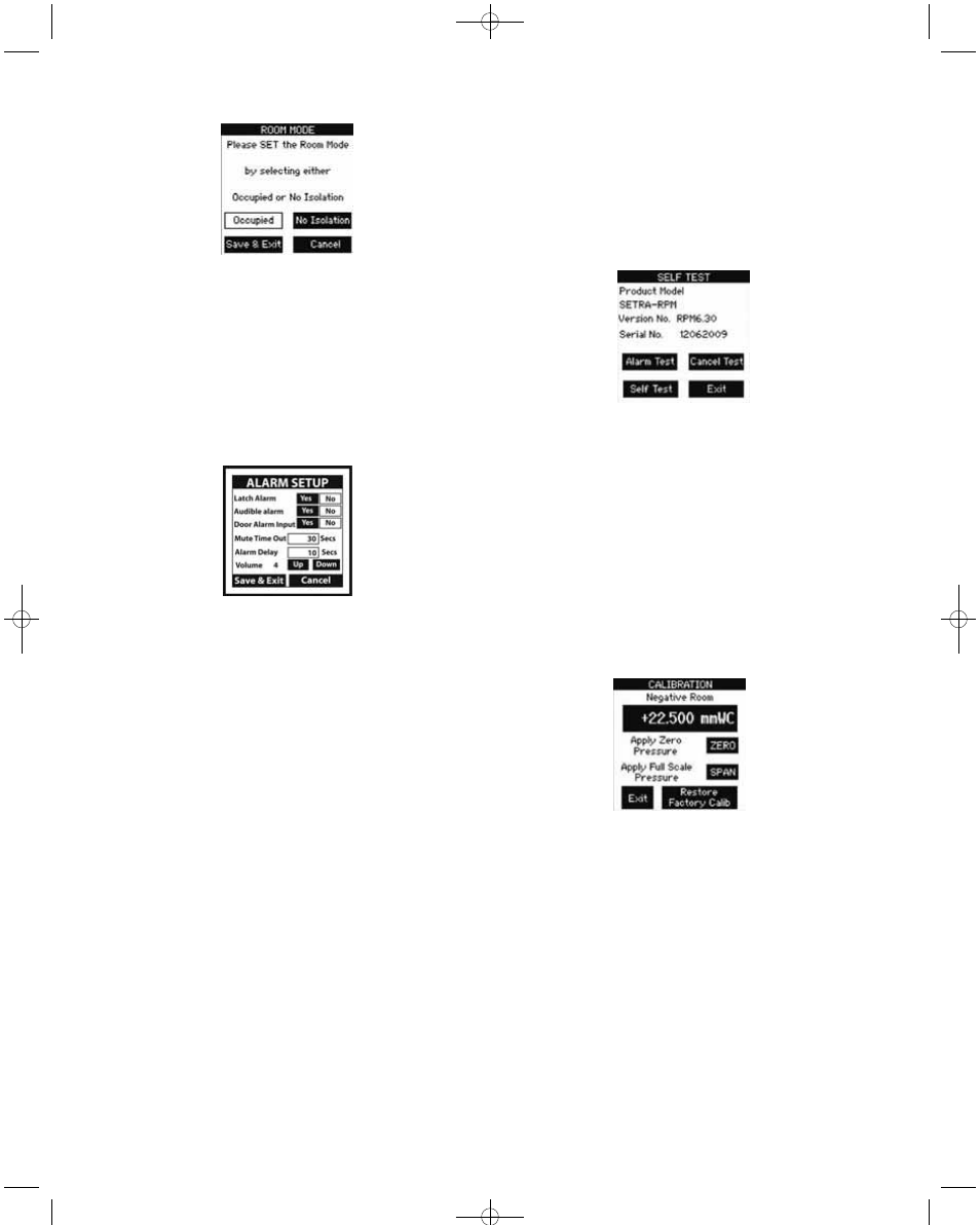
7.4.3 ROOM MODE SCREEN
OCCUPIED/NO ISOLATION
Use these buttons to quickly change the room to standby or no isolation
status. If No Isolation is used there will be no alarms generated if the room
is outside pressure limits.
Press Save and Exit.
OPERATOR PASSWORD
The operator can only change the room from occupied to No Isolating and
vice versa.
7.5 ALARM SETUP SCREEN
From this screen the user can access the following:
a. Latched Alarm requires the pressure to return to normal and the alarm
to be acknowledged before the alarm can be silenced and reset.
b. Enable the audible alarm by selecting “Yes” or use visual only alarm by
selecting “No”.
c. Provide a door “open” pre-alarm visual indication. When activated, the
door status “open” condition is indicated by the touch screen display
turning from green to yellow, and door open indicated on the monitoring
screen.
d. Set the time (in seconds) that the alarm can be silenced in the latched
alarm mode before the alarm resumes. This assumes that the room static
pressure is still outside the normal or set operating limits. The Mute Time
Out can be set from 0 to 60 seconds.
e. Set the Alarm Delay (in seconds) from the time that the room pressure
goes out of the preset limits until the alarm activates. The alarm delay may
be set from 0 to 60 seconds.
f. Set the alarm volume or sound level. Using the Up and Down keys, the
volume can be set at level 1-4. Level 4 alarm volume is the loudest and
corresponds to a sound level of 85 dB at a distance of 4 inches.
7.5.1 ALARM SETUP OPERATION
Lightly press (or tap) button to select “Yes” or “No” for Latch Alarm, Audible
Alarm, or Door Alarm Inputs. Selected box background will change from
clear to black when selected.
7.5.2 MUTE TIME OUT/ALARM DELAY
Pressing (or tapping) the “Mute Time Out” or “Alarm Delay” box activates
the Data Entry screen to set the time.
7.6 SELF TEST SCREEN
7.6.1 Self Test Operation
This screen identifies the Product Model Part Number and Software
Version. User can also perform a Self Test of the unit to verify that the data
in protected area of the EEPROM memory hasn’t been corrupted and also
test the alarm to verify the sound level and alarm setup.
Press “Self Test” button to initiate EEPROM memory checksum test
sequence.
Press “Alarm Test” to test buzzer, visual Red LED Alarm, and relay output.
This can be used to verify the system in alarm mode.
Press “Cancel Test” to stop the alarm test.
Press “Exit” to return to Main Menu.
7.7 CALIBRATION SCREEN
7.7.1 CALIBRATION
To re-zero the device, disconnect the “room pressure” tube and lightly
press (or tap) the “Zero” button. Then apply a steady full-scale pressure
signal to the “+” or “room pressure” tube or fitting and press (or tap) the
“Span” button. Reconnect the room pressure tube and calibration is
complete. Calibration must be within ±5% of original calibration. The
original factory pressure calibration can be restored, if desired, by pushing
the “Restore Factory Setting” button.
P-3-RSM:TEMPLATE 2/17/11 2:22 PM Page 5