Dwyer RSM User Manual
Page 3
3.5 ATTACHING PRESSURE TUBING
Typically a Room Pressure Snubber (RPS) is installed in the monitored
room.
Always attach tubing to the RSM header and then
place Header onto RSM. This will prevent
overpressure from crimped or collapsed tubes.
Use the following procedure for all room types positive, negative or neutral:
Typically a Room Pressure Snubber (RPS) is installed in the monitored
room. Often stiff nylon 3/4˝ tubing is used for running pressure signals from
the SRPM to the monitored spaces. To prevent buckling and collapse of
this stiff tubing inside the electrical box, use the supplied soft silicone
tubing and tubing adapters to transition from the field tubing to the pressure
fittings on the RSM. Attach pressure tubing as follows:
1. Connect the 1/4˝ O. D. tubing from the RPS to the 4˝ x 4˝ electrical box
for the RSM by pushing the 1/4˝ tube onto one end of the barbed, male to
male, tube adaptor, then push the silicone tube (supplied) onto the other
end. Thread the tubes, with installed adaptor, through the conduit opening
at the bottom of the electrical box.
2. Next push the open end of the silicone tubing onto the RSM pressure
tube header (H1) port labeled “+”. Note: The header is an Electro-
Pneumatic (EP) assembly. “+” indicates (Positive) pressure, and “-”
indicates negative or reference pressure.
3. For the most pressure stable operation, an RPS installed in the
reference pressure area is also recommended. In this case, install the RPS
in a hallway or anteroom. Attach the tube to the RSM in the same way as
in step 2, except attach the tube to the “-” port on the pressure tube header.
Tighten swivel fittings on the assembly if they become loose.
4.0 ALARM RELAY OUTPUT
The Single Pole Double Throw (SPDT) relay output can be used for remote
signaling of alarm condition. A form “C” contact rated at 1A is available.
Connect to J4, P1 and P4 (See Section 13.0).
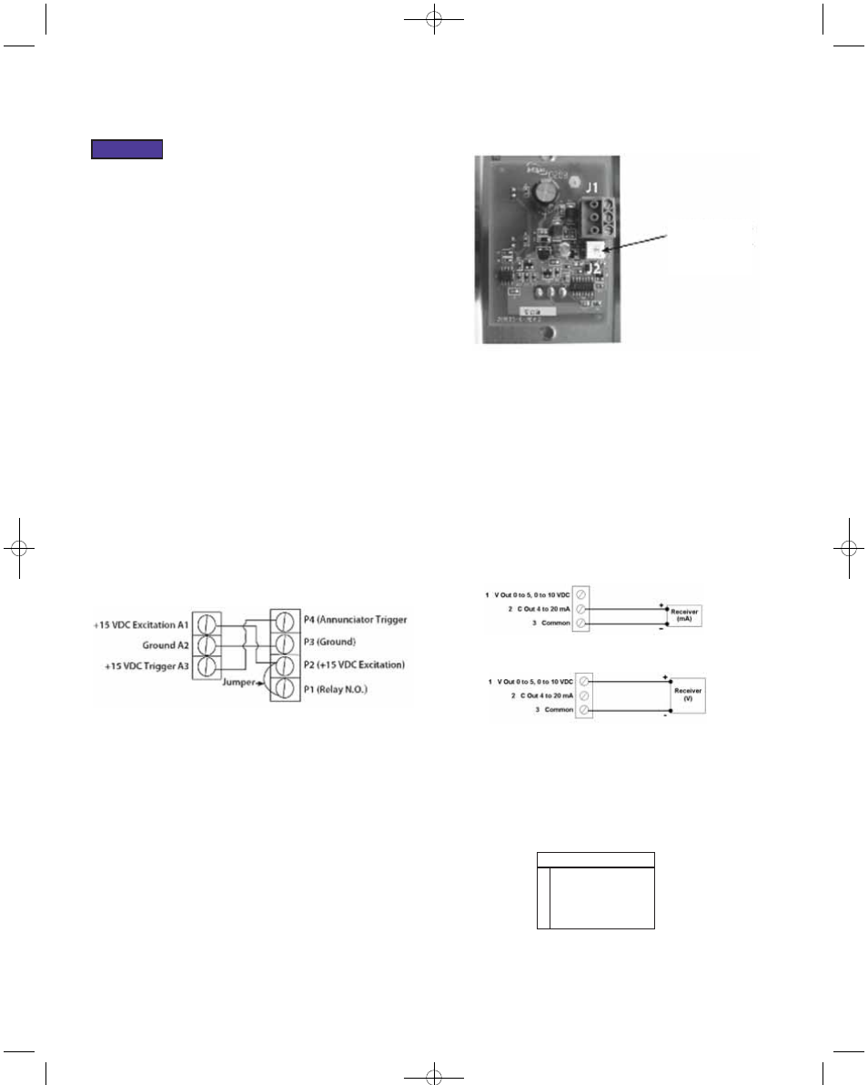
4.1 OPTIONAL REMOTE ANNUNCIATOR WIRING
Dwyer offers an optional Remote Annunciator (Model A-285). In the figure
below, the remote annunciator connector is at left, and the RSM connector
is at right: Connect P1 to P2, then connect P2 to A1 (Located on Remote
Annunciator), finally connect P3 to A2 and P4 to A3.
4.2 AUDIBLE ALARM
Alarm potentiometer can adjust from 0 to 85 dB. Using a screwdriver, rotate
potentiometer (on A-285 remote annunciator PC board) clockwise to
increase volume and counterclockwise to decrease volume.
5.0 DOOR STATUS SWITCH WIRING
5.1 WIRING
Install the door switch into the door jamb. Wire to the normally open (N.O.)
side of the door jamb contact switch. The SRPM will indicate the status of
door position. A contact closure indicates that the door is closed. This is a
low voltage circuit (5 VDC). Run two wires from the door switch to
connector J6 on the SRPM. The door input status function is enabled in the
ALARM SETUP SCREEN, section 7.5.
6.0 ELECTRICAL INSTALLATION
6.1 ANALOG OUTPUT
The RSM can be configured to have current (4 to 20 mA) or voltage (0 to
5 or 0 to 10 VDC) outputs. Voltage output--pin 1, Current output--pin 2,
Common--pin 3. Note: No external excitation is required.
6.2 BACnet Communication
BACnet hardware is implemented as isolated RS485. Wire to Connector
J2, labeled RS-485. Connect tx line to +(A), rx to -(B) and ground wires to
S. Connect Shields together with wire nut. Hardware configuration is done
using a 5 position dip switch located in the upper right hand section of the
PCBA as well as through the touch screen interface.
Use a small flat blade screwdriver or pen to push the switch to the right to
turn that function on, otherwise it is off. There is a BACnet setup screen
that is enabled by pushing position 1 switch to the on position. After
configuration the switch must be moved to the off position.
Current Output
Voltage Output
Audible Alarm
Potentiometer
1
2
3
4
5
MAC address enable
N/C Not Connected
Pull Up Resistor
Termination Resistor
Pull Down Resistor
Position Function
NOTICE
P-3-RSM:TEMPLATE 2/17/11 2:22 PM Page 3