Dwyer MS2-B User Manual
Page 2
electrical Wiring
Figure 1 shows how to connect the MS2 in a network containing a common power
supply. Use a cable containing two twisted pairs. One pair is to be used for B(+)
and A(-). The other pair is to be used for power and common. This configuration is
not suitable for AC supplies. Use a DC supply only. Care should be taken that there
are not too many devices powered from the same supply as voltage drops will
occur in the wiring. If you have many devices, or have long cable runs, the local
supply configuration may be a better choice.
Figure 2 shows how to connect the MS2 in a network containing individual local
supplies. Use a cable containing a twisted pair and a single conductor. The pair is
to be used for B(+) and A(-). The single conductor is to be used for common. Both
AC and DC supplies are suitable for this configuration.
In either configuration you must use shielded cable. The MS2 has a shield terminal
for a convenient location to make connections. It is not electrically connected to the
MS2. Connect the shield to earth ground at one location only to prevent ground
loops.
All devices in the network should be daisy chained. Star connections and T
connections are not permitted.
The B(+) and A(-) lines must be terminated at both ends with a 120 ohm resistor.
If the MS2 is an end device it has an on-board resistor that may be used. See DIP
SWITCH SETTINGS to enable it.
The network must be biased properly. If needed, there are bias resistors on-board
the MS2. No more than two sets of bias resistors should be enabled in the network.
See DIP SWITCH SETTINGS to enable them.
Dip Switch Configurations
Use the left DIP Switch SW1 to configure the BACnet MS/TP MAC communication
protocol address of the device. The LCD will show the address when the
transmitter is powered on. Valid addresses range from 1 to 127. By default, the
device is shipped with the address 127 (as shown in Figure 3). A valid and unused
address should be set before connecting to an existing network. However, the
address can be changed while the device is operational. If the address is changed,
the device will stop responding to the currently configured address immediately.
The device waits 15 seconds after the last switch change before applying the new
address. The device will not function properly if an invalid address is set. The red
LED will periodically blink once indicating an invalid address. The LCD will display
“A Err” when the transmitter is powered on if the address is invalid. See Appendix
I for setting the BACnet MS/TP MAC address of the device.
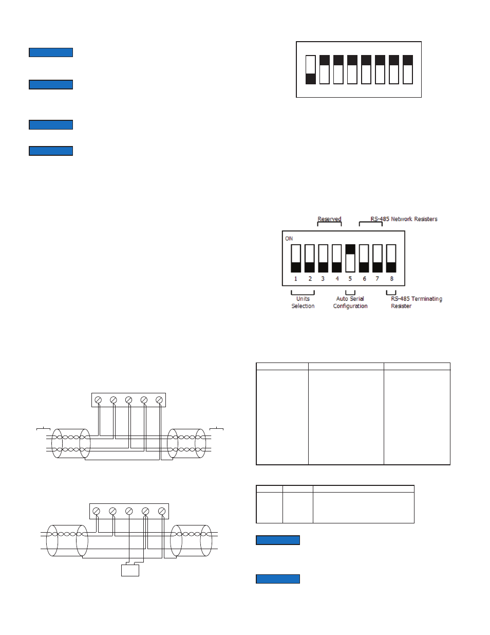
Use the right DIP Switch SW2 to configure other hardware and software options.
Table 1: DIP Switch SW2 functions
Table 2: Display Units Selection
Wiring should comply with Electrical Characteristics of
Generators and Receivers for Use in Balanced Digital Multipoint
Systems, TIA/EIA-485-A-1998, Telecommunications Industry Association, 1998.
NOTICe
Wiring should comply with ANSI/ASHRAE Standard 135-2010
BACnet A Data Communication Protocol for Building
Automation and Control Networks, American Society of Heating, Refrigerating and
Air-Conditioning Engineers, Inc., 2010.
NOTICe
Communications wiring must be in a daisy-chain fashion. Star
connections are not permitted.
NOTICe
Cable shield must be connected to earth ground at one location
only.
NOTICe
COMMON POWER SUPPLY
B(+)
A(-)
PWR
COM SHIELD
TO NEXT
DEVICE
TO PREVIOUS
DEVICE
B(+)
A(-)
PWR
COM
B(+)
A(-)
PWR
COM
figure 1
B(+)
A(-)
PWR
COM SHIELD
POWER
SUPPLY
LOCAL POWER SUPPLY
+ -
B(+)
A(-)
COM
B(+)
A(-)
COM
figure 2
ON
1
2
3
4
5
6
7
8
figure 3
figure 4
Switch
1-2 – Display Units
Selection
(See Table 2)
3-4 – Reserved
5 - Reset BACnet
Configuration to
factory defaults
6 - B(+) Network
Resister
7 - A(-) Network
Resister
8 - Terminating
Resister
On
Reset settings at Power On
511Ω Pull-up to 5V
511Ω Pull-down to GND
120Ω between A(-) and B(+)
When using the on-board buttons, there is a 5 second delay
from the time the zero or span calibration button is released until
the time that the change in calibration takes place. This delay is used to prevent
stress related offsets on the lower ranges.
NOTICe
The security level that is set in the Programming Menu Section
of the manual will determine which calibrations, if any, may be
adjusted by the user through the on-board buttons, but the calibration can be
changed at any time through the communications.
NOTICe
Off
Settings Preserved
Pull-up not connected
Pull-down not connected
Open
Switch 1
OFF
ON
OFF
ON
Switch 2
OFF
OFF
ON
ON
Unit
Inches of Water Column (in WC)
Pascal (Pa)
Millimeters of Water Column (mm WC)
Kilo-Pascal (kPa)