Dwyer ISDP User Manual
Page 4
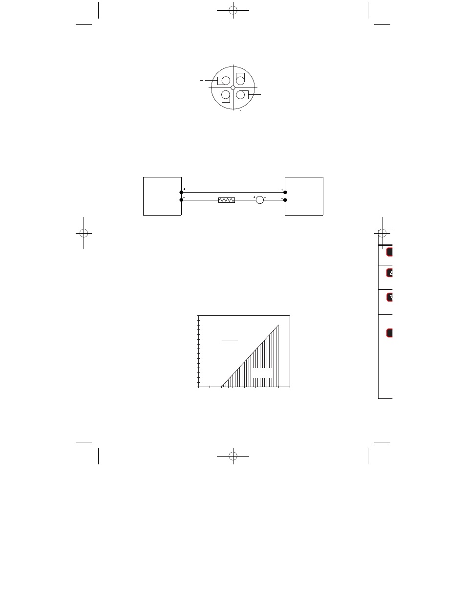
MAXIMUM VALUE (1250Ω)
OPERATING
REGION
R
L
MAX=
Vps-10.0
20mA DC
VDC
0
5
10 13 15
20
25
30
35
TO
T
A
L R
E
C
EIVE
R
R
E
SIST
AN
C
E (
Ω
)
1500
1400
1300
1200
1100
1000
900
800
700
600
500
400
300
200
100
50
40
ISDP
TRANSMITTER
RECEIVER
POWER
SUPPLY
10-35 VDC
mA
SP/AL
ME
MENU
E
RST
PAGE 1 OF 12
8/25/03
SP/AL
MENU
E
RST
PAGE 1 OF 12
8/25/03
SP/AL
MENU
E
RST
PAGE 1 OF 12
8/25/03
SP/AL
MENU
E
RST
PAGE 1 OF 12
8/25/03
ME
UP
ARR
DOW
ARR
ENT
3
2-Wire Operation- An external power supply delivering 10 - 35 VDC with minimum current
capability of 40 mA DC (per transmitter) must be used to power the control loop. See Fig.
C for connection of the power supply, transmitter, and receiver. The range of the appropri-
ate receiver load resistance (RL) for the DC power supply voltage available is expressed
by the formula and graph in Fig. D.
POWER SUPPLY VOLTAGE - VDC (2-WIRE CONNECTION)
A-231 M-12 Cable Colors
PIN 1 is Brown (positive)
PIN 3 is Blue (negative)
Use Model A-231 shielded cable with 4 pin Female M-12 connection.
M-12 Connector
2-WIRE CONNECTION
Fig. C
INST
Mou
or vi
Pres
Use
with
3
2
1
4
+
Fig. D
A-25:B-32 5/8/09 11:22 AM Page 4