Dwyer 43000 User Manual
Page 4
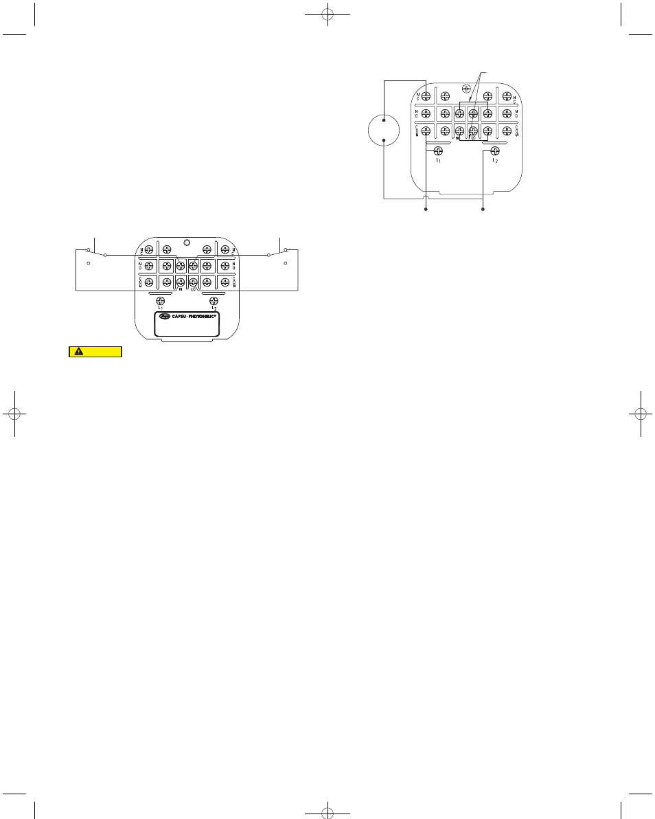
6. Dual Set-Point Manual Reset: Circuit Style HH may also be used for manual reset
applications where it is desired to have maintained contact on either relay following
pressure increase above its set-point. Load or signal connections are made to the
appropriate terminals in Sections A and D (as in paragraph 5 above). Connect
terminals in Sections B and C through normally closed switches or push buttons as
shown in Figure 8. Use of “dry-circuit” type switches such as Dwyer Part No. A-601
with paladium, gold, etc. or rotary wiping action type contacts is recommended.
Make external ground connections as required and connect power to Section E for
the control unit.
Circuit Style LL is used for manual reset applications which require that contact be
maintained following pressure decrease below the set-point. Load connections are
made to the appropriate terminals in Sections A and D. A normally open type
manual reset switch such as Dwyer Part No. A-601 is connected to the terminals
in Sections B and C. The circuit must be “armed” by momentarily closing the switch
while the black pointer is to the right of the set-point. From that point on, the circuit
will latch on pressure decrease below the set-point and remain latched on pressure
increase until manually reset with the optional switch.
7. Dual Set-Point Automatic and Manual Reset Combinations: Circuit Style HH
may be used with either set-point wired and operating as in paragraph 5 above and
other set-point wired and operating as in paragraph 6.
8. High Low Limit Control – Dual Set-Point: Circuit Style HH may be used to control
fans, dampers, pumps, etc., between the set-points of a Capsu-Photohelic
®
.
To accomplish this, use one set-point relay to reset the other as shown in the wiring
diagram Figure 9. In this typical application, the load (for instance a fan) would be
connected to the N.C. contacts for the right set-point relay, Section A (Figure 6). On
pressure rise to the right set-point, its relay would pull in and hold even though
pressure might then fall below that set-point. If the pressure continued to fall to the
left set-point, its relay would automatically be DE-ENERGIZED, return to its normal
position and in so doing, open the holding coil circuit from Section B (Figure 6). The
right set-point relay would thus be reset and the cycle could repeat.
9. Dual Set-Point Special Purpose Circuits: Circuit Style LL may be used where
manual reset following maintained contact on pressure decrease to either set-point
is desired. Circuit Styles HL and LH are combination units. For special
combinations of features, special units, and detailed instructions regarding their
use, consult the factory.
10. Single Set-Point Photohelic
®
: The single set-point Capsu-Photohelic
®
is furnished with the right set-point only. Terminals in Section A and B (Figure 6)
are connected to this relay. Circuit Style SRH is wired for automatic reset as in
paragraph 5 above. Manual reset is accomplished by adding a normally closed
reset switch or push button to the circuit as described in paragraph 6 above.
11. Single Set-Point Special: Manual reset after actuation on falling pressure can be
obtained by using Circuit Style SRL. Consult the factory for special units and
detailed instructions regarding their use.
12. Placing in Service: In normal operation each relay is de-energized when the
pressure applied to the instrument is below its set-point. Special low-latching units
will ordinarily have to be reset before placing on the line in normal operation.
13. Failure Mode: The Capsu-Photohelic
®
circuit design provides certain
protection in the event of a loss of pressure or electrical power. In either case,
both relays will de-energize, returning to their normal "zero pressure" state. The
exceptions to this are models with center zero ranges. Because the relays on all
standard models are always energized when the indicating (black) pointer is to
the right of their respective set-points, the relay action on loss of pressure will
depend on set-point position, since either of them could be located to the left of
zero. As an example; if the left pointer were set at -2 in. w.c. and negative pressure
was -3 in. w.c., a loss of that pressure would allow the black pointer to return to
the center and thus cause the low set-point relay to energize.
If the LED should fail, only the left-low relay will de-energize. The right-high relay
will react as if pressure were above its set-point and will remain energized even
though pressure might be below that setting. In this situation, only termination of
electrical power will allow the right-high relay to de-energize.
MAINTENANCE/REPAIR
Upon final installation of the Series 43000 Capsu-Photohelic
®
Switch/Gage, no routine
maintenance is required. The Series 43000 is not field serviceable and should be
returned if repair is needed (field repair should not be attempted and may void
warranty.
WARRANTY/RETURN
Refer to “Terms and Conditions of Sales” in our catalog and on our website. Contact
customer service to receive a Return Goods Authorization number before shipping
the product back for repair. Be sure to include a brief description of the problem plus
any additional application notes.
RESET
RESET
NC
NC
NO
NO
Manual Reset with Circuit HH
Figure 8
Do not apply electrical current to terminals in Sections B and C.
CAUTION
RESET JUMPER
117 VOLT LINE
1/6 HP*
117 VOLT
LOAD
High-Low Limit Control
Figure 9
(Circuit HH)
*Note: For larger motors, use the Capsu-Photohelic
®
in a maintained contact, 117
Volt Control or Push Button Circuit of the motor starter.
B-34:E-56atex 2/22/11 9:15 AM Page 4