Installation – bsp25, Installation - bsp15 – Blue Angel Pumps BSSF20 User Manual
Page 2
hole, and secure with nut. Make sure
that float switch is above pump base
and that power wires do not interfere
with float switch or pump inlet.
Installation – BSP25
Installation of this
unit may take
several hours. Before disabling your
main pump, have ready an appropriate
means of evacuating the sump.
1. Turn power to main pump off.
2. Pump must be installed using 1-1/4”
or 1-1/2” rigid PVC piping.
PUMP INSTALLATION
The BSP25 can be installed as a back-up
system with a separate dedicated discharge
line (Method 1), or tied into an existing
sump pump line (Method 2, Page 3).
Unplug the existing
AC pump. Failure to
follow this warning could result in fatal
electrical shock.
1. Verify that the existing AC pump
is in good working order. If the AC
pump is questionable, it is typically
recommended that the unit be
replaced with a 1/3 or 1/2 HP pump.
2. Remove any silt or accumulated
debris from the sump pit and
surrounding area.
Method 1 (Preferred)
1. Place the back-up pump on a solid,
level surface in the sump pit. Do
not place the pump on a loose or
sandy surface. Small stones or sand
may damage the pump resulting in
potential pump failure.
2. This pump has a 1-1/2 in. NPT
discharge. If a 1-1/4 in. discharge
pipe is desired, an adapter (sold
separately) will be necessary.
Smaller diameter piping will reduce
pump flow, rate and performance.
3. Cut a 4 ft. section of 1-1/4 in. or 1-1/2
in. diameter rigid PVC pipe. Cement
1-1/4 in. pipe to a threaded fitting.
Cement 1-1/4 in. pipe into pipe
coupling. Attach 1-1/4 in. pipe section
to the BSP25 discharge adapter.
4. Screw PVC pipe onto pump discharge.
Be careful not to
strip or cross thread
plastic fi ttings or check valves. Flex
hose is not recommended. Rigid PVC or
metal pipe is required for a permanent
installation.
5. Place the pump with the 4’ section of
PVC pipe on a solid, level surface in
the sump pit on an elevated surface.
2
Operating Instructions and Parts Manual
5. Insert flapper valve into tee. Be sure
locator tab is in the notch of the tee
fitting (see Figure 2).
6. Slide clamp onto tee.
7. Insert pump into flapper valve, tilt
pump 30˚. When tilted, the side with
the power cord should be up (see
Figure 3). Tighten clamp around the
pump and flapper valve (see Figure 2).
Pump must be
tilted as shown in
Figure 3 to prevent air locking.
8. To install float switch for standby
pump, first slide bracket into slot on
top of tee. Secure bracket with screw
provided. Remove top hex nut from
switch and slide the cord up and out
of the way. Slip cord through slot in
bracket, pull threaded stud through
6. Attach a rubber check valve (sold
separately) to the top of the discharge
pipe. This will allow the pump or check
valve to be removed easily for servicing.
NOTE: Check valves can be placed directly
in the pump discharge if desired. However,
for ease of disassembly, it is recommended
that check valves be placed above the
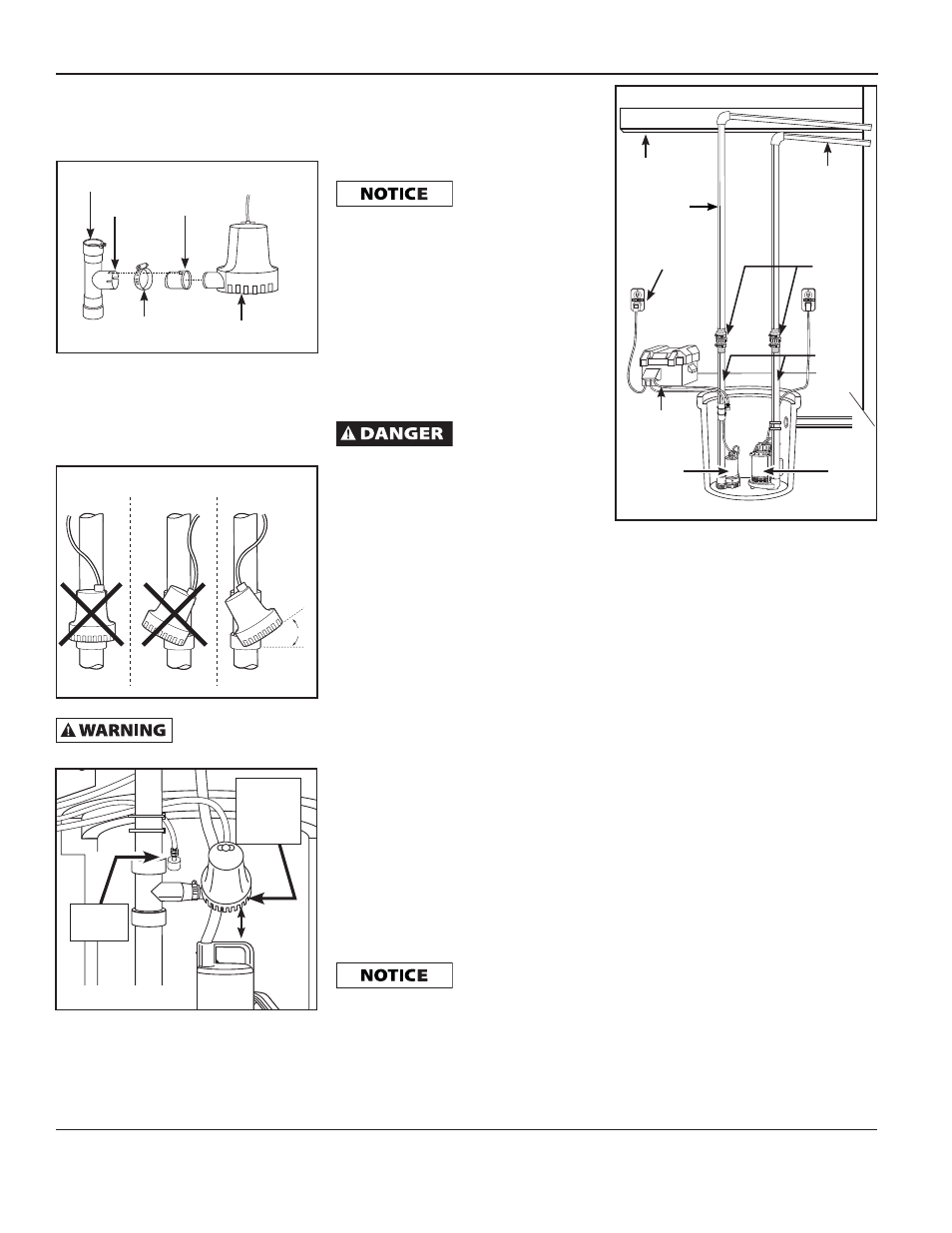
sump as shown in Figure 1, page 1.
The remainder of the discharge pipe
installation will vary depending on
individual circumstances. Using sound
plumbing practices, route the discharge
pipe to an exterior wall by the shortest
path. Keep turns to a minimum because
they reduce flow output of the pump.
The pipe that exits the building
structure should be sloped downward so
that water will not freeze in the pipe.
When installing the separate discharge
pipe, drill through the outside wall with
appropriate drilling equipment. Seal the
hole to prevent water from entering.
Method 2
If a separate, dedicated discharge is not
possible as in Method 1, the BSP25 pump
can be tied in to the primary pump’s
discharge pipe by installing a “Y” connector.
Two check valves will be required.
1. Locate the BSP25 on a solid, level
surface in the sump pit. Do not
place the pump on a loose or sandy
surface. Small stones or sand may
damage the pump resulting in
potential pump failure.
www.blueangelpumps.com
Installation - BSP15
(continued)
Figure 2
TEE FITTING
NOTCH
FLAPPER VALVE
LOCATOR
TAB
CLAMP
BACK-UP
SUMP PUMP
30˚
Figure 3
INCORRECT
CORRECT
Figure 4
BACK-UP
SUMP
PUMP
INLET
FLOAT
SWITCH
1 IN. MIN.
Figure 5
RIGID
PVC PIPE
CHARGER
SLOPE
DOWN
PIPE
CHECK
VALVE
1-1/4"
OR
1-1/2"
PVC
PIPE
FLOOR
JOIST
BATTERY
BOX
BACK-UP
PUMP
PRIMARY
PUMP
INCORRECT