Installation, Wiring to tb1, Wiring to tb2 – Badger Meter Research Control Valve User Manual
Page 8: Wiring to tb3, Installation 8, Wiring to tb1 8 wiring to tb2 8 wiring to tb3 8
INSTALLATION
Qualified personnel must perform all wiring in accordance with prevailing codes
Fusing must be installed in line power, and should be of the slow-blow type Badger Meter recommends 1 amp for AC input
models and 5 amp for DC input models
Wiring should be routed to the actuator through one of the two 1/2 inch conduit openings Generally, one conduit contains
input power and earth ground wires The other conduit contains low level input and output signal wiring
All low level signal wiring should be a shielded type with the shield grounded at source common After installation, seal all
conduits to prevent water damage
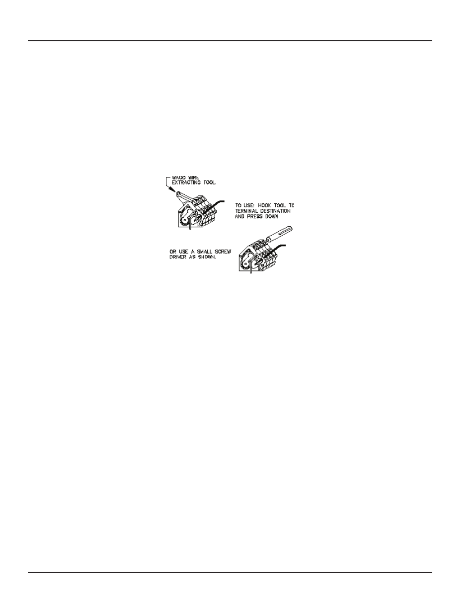
Strip 0 22 inch (5 6 mm) of insulation from the wire and insert the bare end into the appropriate terminal location, using an
insertion tool or a small screwdriver as shown below
Maximum recommended wire size is 14 AWG, and minimum is 26 AWG
Wiring to TB1
Input power terminates at TB1 For AC models, terminal 1 is line, and terminal 2 is neutral The incoming power supply earth
ground should be securely connected to the green ground screw located inside the actuator base between the two conduit
entries For DC models, terminal 1 is positive (+), and terminal 2 is negative (–) Terminal strip tabs are pressed down to
insert wires
Wiring to TB2
LS1 and LS2 are factory-wired as end-of-travel limit switches
OTEE:
N
Because amplifier ZERO and SPAN setpoints are always active, LS1 and LS2 must be set within ZERO and SPAN of the
amplifier
Current command (4…12 mA, 12…20 mA, or 4…20 mA) wiring terminates on terminals 3 (–) and 4 (+) Voltage command
(0…5V DC or 1…10V DC) wiring terminates on terminals 5 (+) and 6 (–)
Wiring to TB3
If LS3 and LS4 are used as auxiliary position limit switches, connection is to terminals 1 through terminal 4 Maximum voltage is
40V DC and maximum current is 40 mA The 4…20 mA position feedback signal wires connect to terminals 9 (+) and 10 (–)
Increasing command signal will result in an increasing position feedback signal Operation of the transmitter requires
an external DC power supply in the range of 12…36V DC and a positive load connected in series with one lead from the
power supply
Electronic Valve Actuator, Model EVA 100/200
Page 8
February 2014