Startup, Low level current or voltage command signals, Startup 10 – Badger Meter Research Control Valve User Manual
Page 10: Low level current or voltage command signals 10
STARTUP
Low Level Current or Voltage Command Signals
1. Power
Before applying AC power to TB1 of the upper power supply board, set the slide switch to the correct voltage
2. Auto Switch
Place DIP Switch 1 to ON (Down) to place actuator in AUTO mode
3. Setpoints
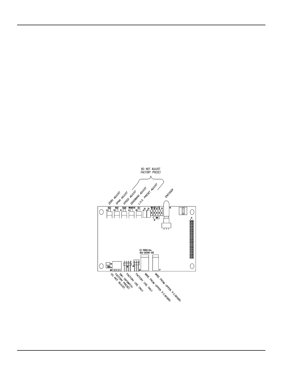
These are the end-of-travel extremes corresponding to the actuator output shaft positions for low (typically 4 mA) and
high (typically 20 mA) command signal levels They are set by the ZERO and SPAN push-buttons and encoder All settings
require holding a push-button and turning the encoder
a Set the command signal to the lowest level, normally 4 mA
b To adjust the LO setpoint (ZERO), press and hold the ZERO push-button (S1) and turn the encoder to move the
actuator's output shaft into position Turn the encoder clockwise (CW) to extend the output shaft or counter-clockwise
(CCW) to retract the output shaft Release the push-button
c Set the command signal to the highest level, normally 20 mA
d To adjust the HI setpoint (SPAN), press and hold the SPAN push-button (S2) and turn the encoder to move the
actuator's output shaft into position Turn the encoder CW to extend the output shaft or CCW to retract the output
shaft Release the push-button
4 Deadband
The deadband adjustment establishes the actuator servo sensitivity It is factory set at 1% and should not be field
adjusted If the actuator begins to oscillate (Green and Yellow LEDs turn on and off rapidly), decrease the sensitivity by
holding deadband push-button (S4) and turning the encoder CW until the oscillation stops Release the push-button
5. Speed Adjust
Speed is preset at the factory To adjust the speed, press and hold the SPEED push-button (S3) and turn the encoder CW to
increase or CCW to decrease the actuator speed
Electronic Valve Actuator, Model EVA 100/200
Page 10
February 2014