Badger Meter 7500 Series Mag Meter User Manual
Page 7
7500P MAG METER STANDARD SWITCH SETTINGS
½" Meter
(1-30 gpm)
Pre Selection Factor
Jumper Position
1 Pulse Per Gallon
1500
D
10 Pulse Per Gallon
1500
D
100 Pulse Per Gallon
0150
D
500 Pulse Per Gallon
0030
D
1 Pulse Per Liter
3965
D
1" Meter
(3-80 gpm)
1 Pulse Per Gallon
6000
D
10 Pulse Per Gallon
0600
D
100 Pulse Per Gallon
0060
D
500 Pulse Per Gallon
0012
D
1 Pulse Per Liter
1585
D
2" Meter
(10-315 gpm)
1 Pulse Per Gallon
0750
C
10 Pulse Per Gallon
0075
C
1 Pulse Per Liter
0075
C
3" Meter
(24-690 gpm)
1 Pulse Per Gallon
0380
B
10 Pulse Per Gallon
0038
B
1 Pulse Per Liter
0038
B
4" Meter
(40-1200 gpm)
1 Pulse Per Gallon
0250
A
10 Pulse Per Gallon
0025
A
1 Pulse Per Liter
0025
A
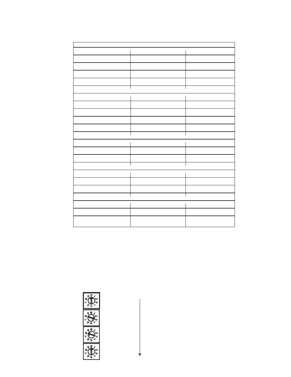
PRE-SELECTION SWITCHES
On the board diagram on the previous page, note the po-
sition of the (4) "Pre-Selection Rotary Switches." As per
the above chart, these switches are set at the factory per
meter size and general magnitude of pulse output desired.
If a change of resolution (pulse output value) is required,
change the Pre-Selection Switches to above values.
7
Example:
Setting of Pre-
selection Rotary
Switch Settings
3" Meter with
1 pulse/gallon = 0380
1��
0
10��
8
100��
3
1000�
0
JUMPER LOCATION
Please note in the illustration the jumper area. There are
(4) jumper positions designated by A, B, C, and D.
The
jumper must be located in the correct position for the
respective meter size. The "D" position is for 1/2" and
1" meters. The A, B, and C positions are for 4", 3" and 2"
sizes respectively. See chart above.