Installation instructions, double support – Badger Meter AS - Steam (2 to 72")" User Manual
Page 6
INSTALLATION INSTRUCTIONS, DOUBLE SUPPORT
1 . Follow steps 1 through 7 in
“Installation Instructions, Single Support” on page 5
. At 180° from and on the same plane
as the previously drilled hole, grind the surface of the pipe to provide a clean area for welding . Drill a hole and deburr,
especially on the inside of the pipe . Size the hole used for the double support according to
2 . Weld the double support weld-o-let, making sure that it is centered with the drilled hole (1/16" weld gap recommended) .
Model / Sensor
Weld Connector
Drill Bit
AS (7/8")
1/2"
1/2"
AS1 (1-1/4")
1"
7/8"
Table 3: Double support drill bit size
3 . Install the AS Ellipse sensor through the two holes . Make sure that the double support pin passes through the guide ring .
See
Ellipse Sensor
Double Support Pin
Guide Ring
Figure 6: Double support pin
4 . While holding the AS Ellipse in its fully inserted position, align the sensor head with the direction of flow as in step 9,
“Installation Instructions, Single Support” on page 5
5 . Check that the AS Ellipse is in the correct orientation and spans the inside of the pipe . Tighten the compression nut
manually, then use a wrench to tighten it another 1-1/4 turns .
6 . Install the plug into the end of the double support weld-o-let . Tighten the plug to prevent leakage . Ensure that there is no
leakage in the system .
7 . Follow steps 11 through 15 in
“Installation Instructions, Single Support” on page 5
.
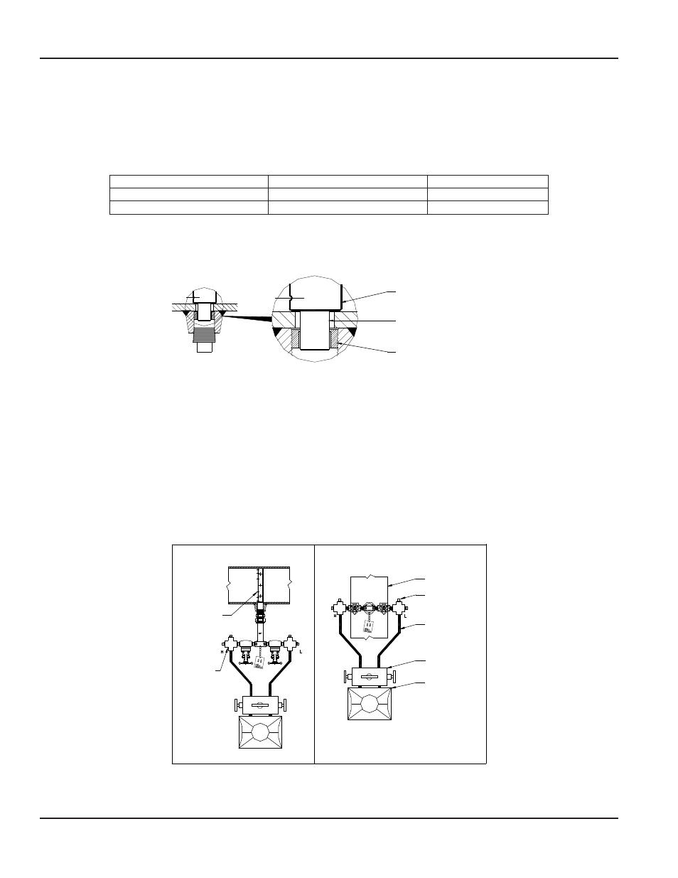
TYPICAL INSTALLATION WITH DIFFERENTIAL PRESSURE TRANSMITTER
Horizontal Pipes
Vertical Pipes
Ellipse
Sensor
Cross Tees
Pipe
Fill here
with water
1/2" Tubing
3- or 5-Valve
Manifold
DP Transmitter
Figure 7: Installation with differential pressure transmitter
Ellipse® Pitot Tube Meter, AS Annular Threaded Steam Meter
Page 6
April 2014