Installation instructions, single support – Badger Meter AS - Steam (2 to 72")" User Manual
Page 5
INSTALLATION INSTRUCTIONS, SINGLE SUPPORT
1 . Choose the proper location to install the AS Ellipse using AGA/ASME standards (or equivalent) . See
2 . Grind the surface of the pipe where the AS Ellipse is to be inserted to provide a clean area for welding .
3 . Weld the supplied weld-o-let to the pipe using standard codes for your application (1/16" weld gap recommended) . Take
care to protect the threads during the welding process .
4 . Drill a hole through the pipe wall according to
.
5 . Deburr the hole just drilled, especially on the inside of the pipe .
Model / Sensor
Weld Connector
Drill Bit
AS (7/8")
1"
1-1/8"
AS1 (1-1/4")
1-1/4"
1-3/8"
Table 2: Single support drill bit size
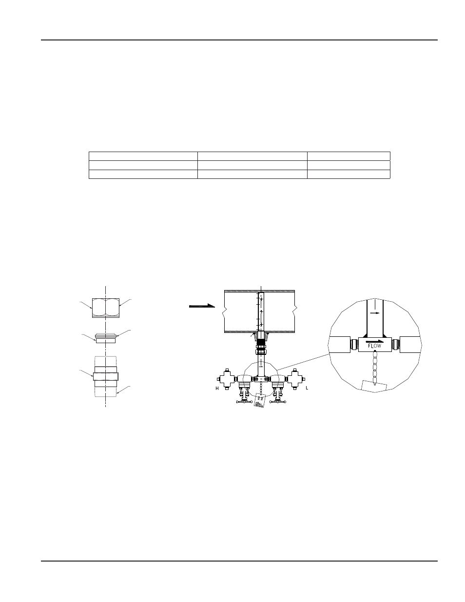
6 . Assemble the supplied compression fitting as diagrammed in
. Thread the assembled compression fitting into
the weld-o-let manually . With a wrench, tighten the body of the fitting another 1-1/4 turns, taking care not to tighten the
compression nut .
7 . Install the instrument valves (optional) at the AS Ellipse head connections . Make sure the valves are FULLY CLOSED to
prevent them from leaking during startup . Install the two forged crosses to the valves .
8 . Insert the AS Ellipse through the compression fitting . Carefully push the sensor by hand further into the pipe until it
reaches the opposite wall .
9 . While holding the AS Ellipse in its fully inserted position, align the arrow on the sensor head with the direction of flow . See
Compression
Fitting Nut
Insert
Body
Tighten Nut, as
Shown, onto Body
of the Compression
Fitting
Install Insert
as Shown
Install Threaded
Portion into Weld
Fitting on Pipe
FLOW
Field Weld
Figure 4: Compression fitting
Figure 5: Sensor alignment
10 . To prevent leakage, manually tighten the compression nut, the use a wrench to tighten it another 1-1/4 turns .
11 . Connect the 1/2" tubing to the connections on the forged cross components . Connect these lines to a three-valve
manifold transmitter .
12 . Verify that the instrument valves are FULLY CLOSED . Remove the 1/2" plugs from the top and side ports of the two forged
cross tees .
13 . Slowly pour water into the top ports of each forged cross tee until the system is full . Water will flow out of the side ports of
both crosses .
14 . Reinstall the 1/2" plugs into the top and side ports . Ensure that they are secure . Then fully open the two gate valves .
15 . Allow condensation levels to stabilize for 30 minutes before taking instrument reading .
User Manual
Page 5
April 2014