Calibration, Calibration tables, Calibration table for series 735pv – Badger Meter Series 735 Sensors User Manual
Page 8
CALIBRATION
Badger Meter Impeller sensors use unique K and offset numbers for calibration. These numbers are derived from calibration
runs using NIST traceable instruments. Using both a K and an offset number provides higher accuracy than using a K factor
alone. The K and offset numbers for each tee configuration are listed in the "Calibration Table" below.
Calibration Table Columns
The table below provides calibration and operation data for Badger Meter Plastic Tee Sensors 1-1/2" to 4".
Column 1
Sensor Model Number
Columns 2 and 3 The K value and Offset values to use in our frequency equation:
Freq= Gpm
K
- offset
This equation describes the frequency of the output signal of all Badger Meter flow sensors. By
substituting the appropriate K and Offset values from the table, the sensor’s output frequency can be
calculated for each pipe size. This information is required when calibrating an output board or when
using the raw sensor data as direct output to interface with a device that is not a Badger Meter product.
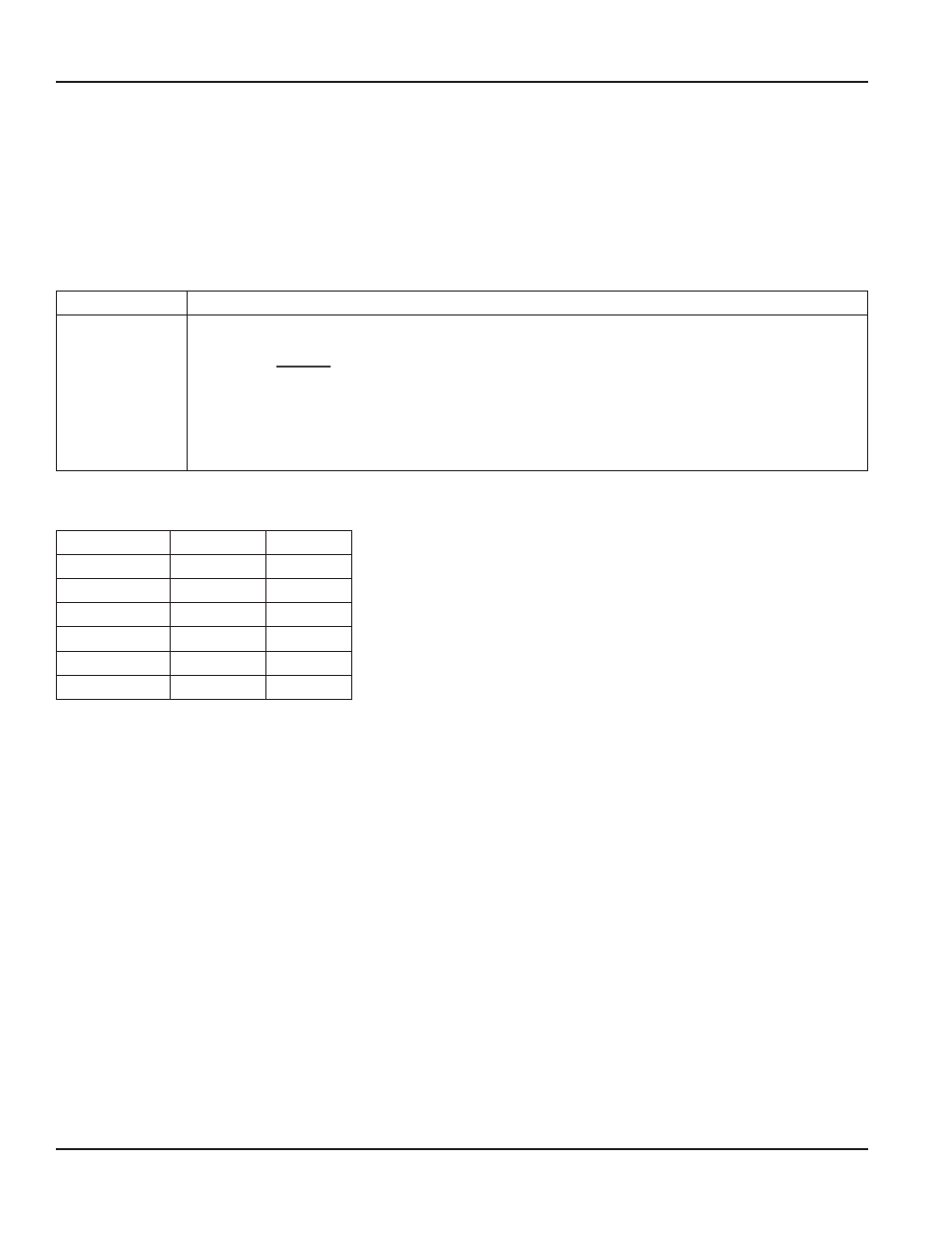
Calibration Table
Size/Schedule
K
Offset
1/2" S40
0.078000
0.9
1/2" SDR 13.5
0.120119
0.1
3/4" S40
0.156300
0.9
3/4" SDR 21
0.197000
–0.6
1" S40
0.261119
1.2
1" SDR 21
0.321739
0.6
Series 735PV Plastic Tee Type Impeller Flow Sensor
Page 8
January 2013