Impeller assembly and shaft replacement – Badger Meter Series 4000 Sensor - 1/2, 3/4", 1" User Manual
Page 8
Impeller Assembly and Shaft Replacement
The following tools are required for the replacement of the impeller and shaft: 5/32" Allen wrench, flat blade screwdriver,
torque driver in “in-lb” with 5/32" male hex adapter. Units are factory calibrated at 12in-lbs.
1. Depressurize the pipe on which the sensor is to be serviced.
DO NOT REMOVE SOCKET HEAD CAP SCREWS
WHILE SYSTEM IS UNDER PRESSURE.
2. Using the Allen wrench, loosen and remove the four #10 socket head cap screws along with the stainless steel cover. It is
not necessary to remove the electronics to service the impeller and shaft.
3. Utilizing the provided slots alternately, pry the impeller cover/shaft assembly from the sensor housing with the flat blade
screwdriver.
4. Inspect the impeller and impeller cover/shaft assembly for signs of wear. Replace if necessary. It is good practice to
replace o-rings before reassembling. Use no lubricants on o-rings.
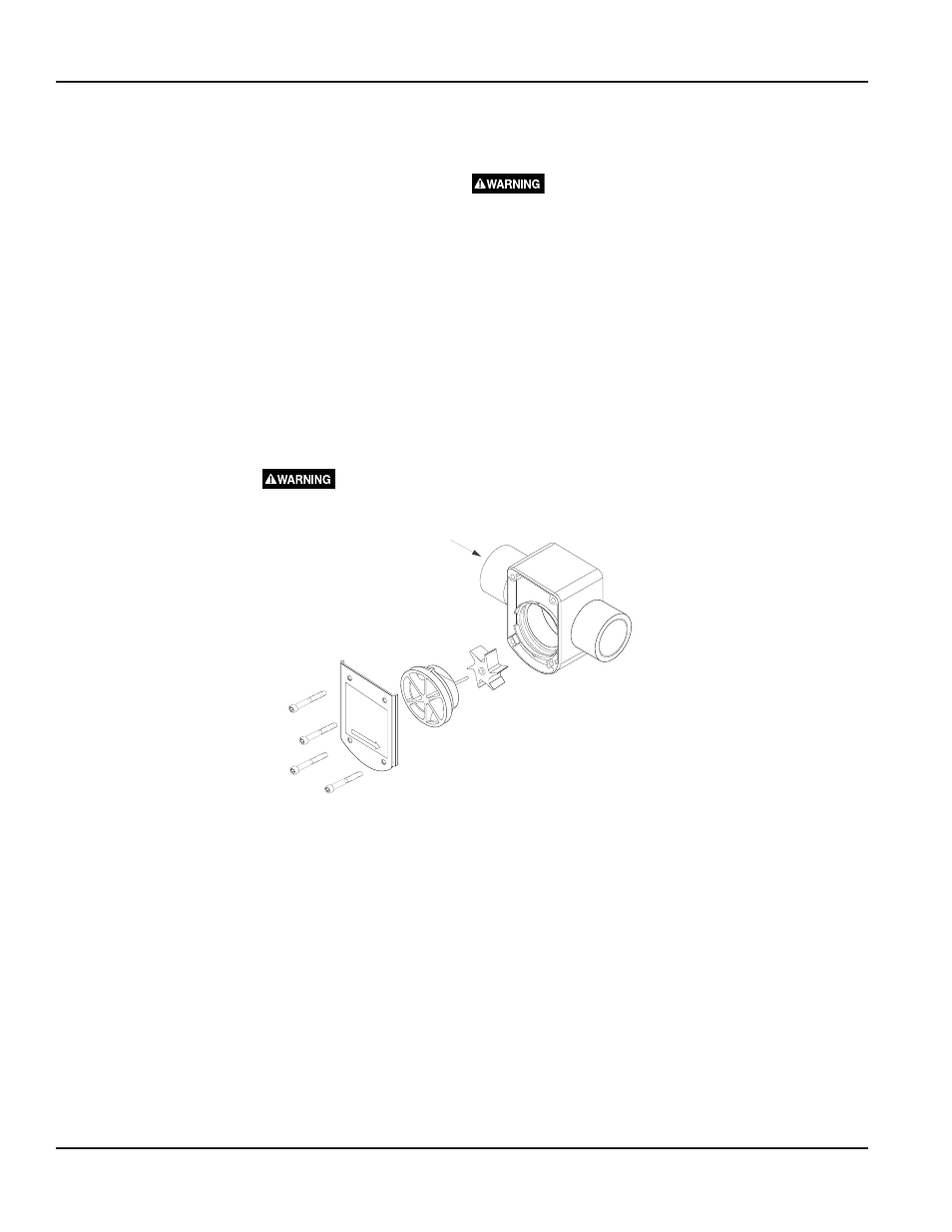
5. To reassemble the sensor, position the impeller into the cavity of the sensor housing, making sure the six blades
are pointing into the flow direction. The unit will not operate if the impeller is positioned incorrectly.
EXAMPLE: If flow direction is to the right, position impeller with blades pointing to the left. (See Figure 3 below.)
6. Orienting the keyway of the impeller cover/shaft assembly to the small slot between the two large slots and aligning the
shaft to the shaft hold of the impeller, hand press the impeller cover/shaft assembly into the sensor housing cavity.
7. Fasten the stainless steel cover to the sensor housing using the #10 socket head cap screws. Torque the #10 hardware to
12 in-lb. pressurize system.
ALL FOUR SCREWS MUST BE IN PLACE AND TORQUED CORRECTLY BEFORE
PRESSURING SYSTEM!
STAINLESS STEEL
COVER
IMPELLER COVER/SHAFT ASSEMBLY
IMPELLER
PVC VERSION
#10 HARDWARE
Flow
Direction
Figure 3: Assembly and Shaft Replacement
Series 4000
Page 8
April 2012