Electrical installation – Badger Meter Series 4000 Sensor - 1/2, 3/4", 1" User Manual
Page 7
ELECTRICAL INSTALLATION
The Series 4000 digital transmitter is supplied with 20 feet of 20 AWG three conductor cable with drain wire and shield. The
Series 4000 analog unit is supplied with 30 inches of cable. Make electrical wiring connections according to accepted trade
practices.
An electrical junction box may be attached directly to the sensor electronic module, or mounted in the vicinity of the sensor.
Locate it conveniently to facilitate replacement of the electronic module assembly. The wiring connections should not be
subjected to water of conductive liquids, as these may impair operations or damage the sensor circuitry.
When connecting to the electronic device, observe the wire colors and polarity to insure proper performance and to prevent
damage to the sensor or electronic device.
Electrical Wiring-Digital Unit
4-20mA power must be off and all wiring should be done before turning on loop power.
1. Refer
to
Figure 2 for illustration of the following instructions.
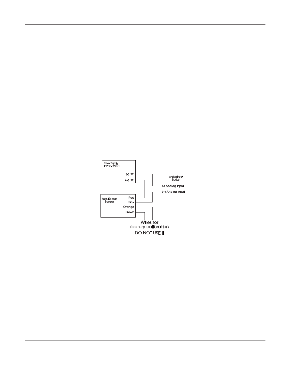
2. Wire
the
Red Wire (+ Analog loop) of the flow sensor to the POSITIVE (+) output of a DC power supply.
3. Wire
the
Black Wire (- Analog Loop) of the flow sensor to the POSITIVE (+) input of your analog device.
4. Wire
the
NEGATIVE (-) input of your analog device to the NEGATIVE (-) of the DC power supply.
5. Electrical installation complete.
(Vintage Units)
Figure 2: Wiring For Analog 4000
NOTE: THERE ARE TWO ADDITIONAL WIRES IN THE SENSOR CABLE (BROWN AND ORANGE). THESE WIRES ARE FOR
FACTORY CALIBRATION ONLY, CONNECTING TO THESE WIRES MAY DAMAGE UNIT AND VOID WARRANTY.
Installation & Operation Manual
Page 7
April 2012