Badger Meter Digital Displays User Manual
Page 3
WIRING THE F6700 / F6750 SERIES DISPLAYS
ACTIVA Flow Sensors, FS Series Flow Sensors and F6100 Series Sensor Arrays Using the
Intelligent Frequency Converter (IFC) Option
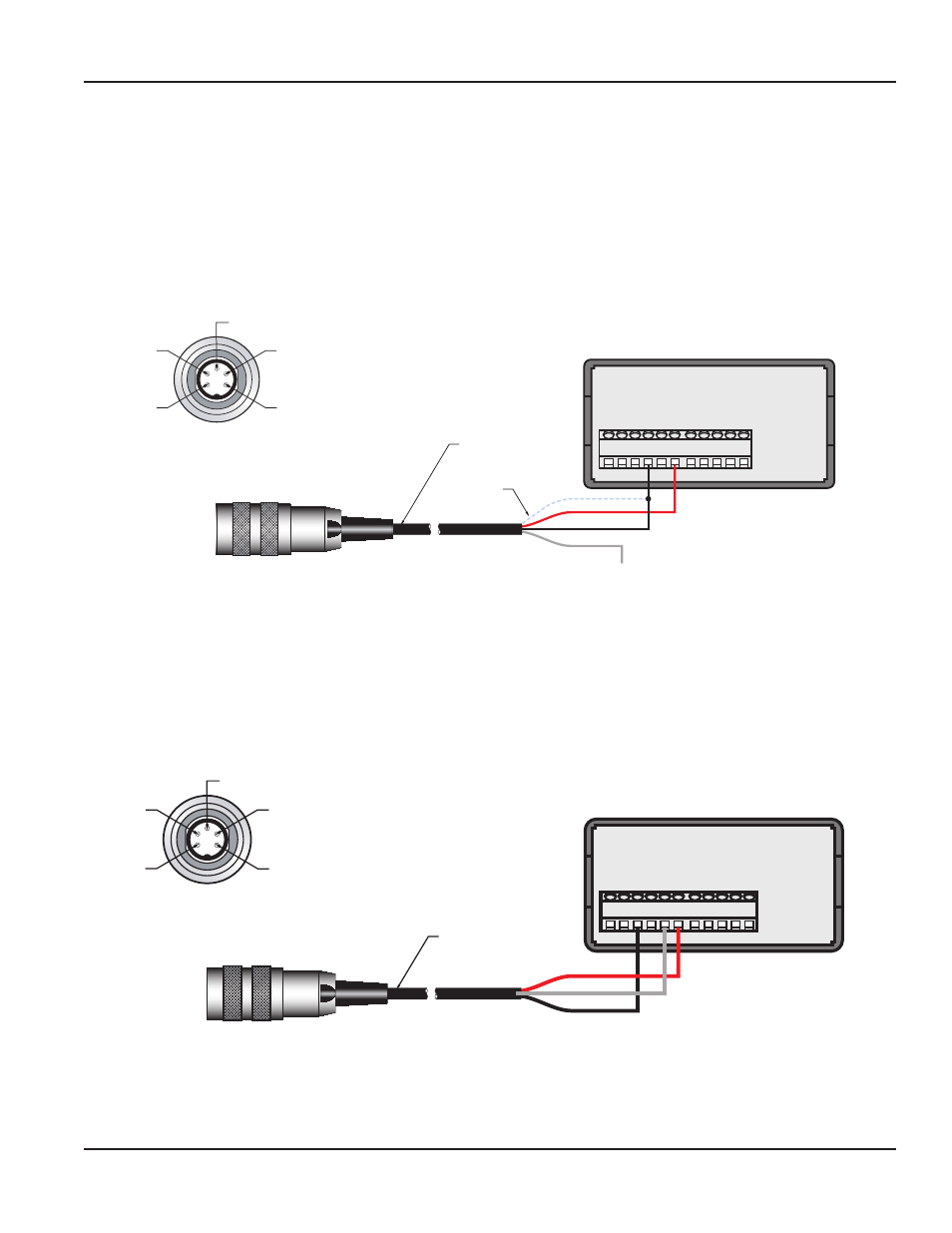
4…20 mA Output
The F6557 cable is a five-pin, three-wire cable used to connect the IFC sensors to the F6700 series displays. Only two of the three wires in
the cable are used.
1. Connect the RED wire of the F6557 cable to terminal 6 (+24 V EXC) on the F6700 series display. See
.
20 mA
COMM.
+24 V
EX
C.
1 2 3 4 5 6
7 8 9 10 11
F6700 / F6750
Series Display
(BLACK) - Loop
(WHITE) N.C.
(RED) + Loop
3
2
1
4
5
Top of
F to I Converter
CABLE ASSEMBLY
F6557-6 6 ft (1.8 m)
F6557-15 15 ft (4.6 m)
Shield
Pin 1 = + 4 - 20 mA (Sink) - RED
Pin 2 = - 4 - 20 mA (Source) - BLACK
Pin 3 = N/C - WHITE
Pin 4 = N/C
Pin 5 = N/C
Figure 3: Flo-tech IFC flow sensor wiring
2. Connect the BLACK wire of the F6557 cable to terminal 4 (20 mA) on the F6700 series display.
3. Connect the SHIELD wire of the F6557 cable to terminal 4 (20 mA) on the F6700 series display.
0…5 Volt Output
The F6557 cable is a five-pin, three-wire cable used to connect the IFC sensors to the F6700 series displays. Only two of the three wires in
the cable are used.
1. Connect the RED wire of the F6557 cable to terminal 6 (+24 V EXC) on the F6700 series
display. See
10 V
COMM.
+24 V
EX
C.
1 2 3 4 5 6
7 8 9 10 11
F6700 / F6750
Series Display
(BLACK) 0-5 VDC Out
(WHITE) Common
(RED) + V
3
2
1
4
5
Top of
F to V Converter
CABLE ASSEMBLY
F6557-6 6 ft (1.8 m)
F6557-15 15 ft (4.6 m)
Pin 1 = + 24V DC - RED
Pin 2 = 0-5 VDC Output - BLACK
Pin 3 = Common - WHITE
Pin 4 = N/C
Pin 5 = N/C
Figure 4: Flo-tech IFC flow sensor wiring
2. Connect the BLACK wire of the F6557 cable to terminal 3 (10 V) on the F6700 series display.
3. Connect the WHITE wire of the F6557 cable to terminal 5 (COMM) on the F6700 series display.
User Manual
Page 3
June 2014
SGN-UM-00979-EN-06