Badger Meter Digital Displays User Manual
User manual, Signal wiring, Wiring overview
WIRING OVERVIEW
Electrical connections are made via screw-clamp terminals located on the back of the display. All conductors should conform to the meter’s
voltage and current ratings. All cabling should conform to appropriate standards of good installation, local codes and regulations. It is
recommended that power supplied to the meter (DC or AC) be protected by a fuse or circuit breaker.
When wiring the display, compare the numbers embossed on the back of the display case against those shown in the wiring drawings for
proper wire position.
Each terminal can accept up to one #14 AWG (2.55 mm) wire, two #18 AWG (1.02 mm), or four #20 AWG (0.61 mm).
1. Strip the wire, leaving approximately 0.3 inches (7.5 mm) bare lead exposed (stranded wires should be tinned with solder).
2. Insert the lead under the screw-clamp terminal.
3. Tighten the screw-clamp until the wire is secure.
4. Pull the wire to verify tightness.
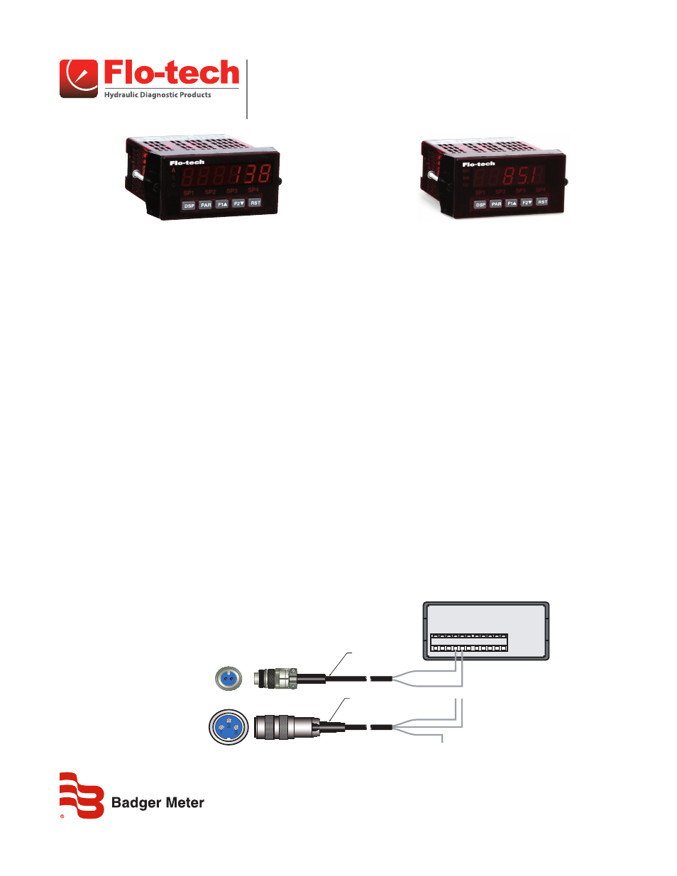
WIRING THE F6600 / F6650 SERIES DISPLAYS
The frequency signal from the Flo-tech FSC, FSB, and FSD series turbines is connected to the display using one of the
F2832 series cables. The Flo-tech Ultima sensor is connected using the F6234 series cables.
FSB, FSC*, and FSD Sensors
Connect the BLUE wire of the F2832 cable to terminal 5 (INPUT A) and the YELLOW wire to terminal 4 (COMM) on the F6600 series display.
See
* Some require the use of the F5140 K-Factor Scaler to ensure adequate signal strength to the display.
Ultima Sensors*
Connect the RED wire of the F6234 cable to terminal 5 (INPUT A) and the BLACK wire to terminal 4 (COMM) on the F6600 series display. See
. The WHITE wire is not used.
* Some require the use of the F5140 K-Factor Scaler to ensure adequate signal strength to the display.
COMM
INPU
T A
INPU
T B
1 2 3 4 5 6
7 8 9 10 11
F6600 / F6650
Series Display
(YELLOW)
-
(BLUE)
+
CABLE ASSEMBLY
F2832-6
6 ft (1.8 m)
F2832-15 15 ft (4.6 m)
(BLACK)
-
(WHITE) N.C.
(RED)
+
CABLE ASSEMBLY
F6234-6
6 ft (1.8 m)
F6234-15 15 ft (4.6 m)
Top of
F6234 Cable
3
2
1
1 - N/C (WHITE)
2 - - (BLACK)
3 - + (RED)
A - + (BLUE)
B - - (YELLOW)
Top of
F2832 Cable
B A
Figure 1: Flo-tech frequency output wiring
Signal Wiring
F6600 / F6650 and F6700 / F6750 Series Displays
SGN-UM-00979-EN-06 (June 2014)
User Manual