Top of f6234 cable, Top of f2832 cable – Badger Meter Digital Displays User Manual
Page 2
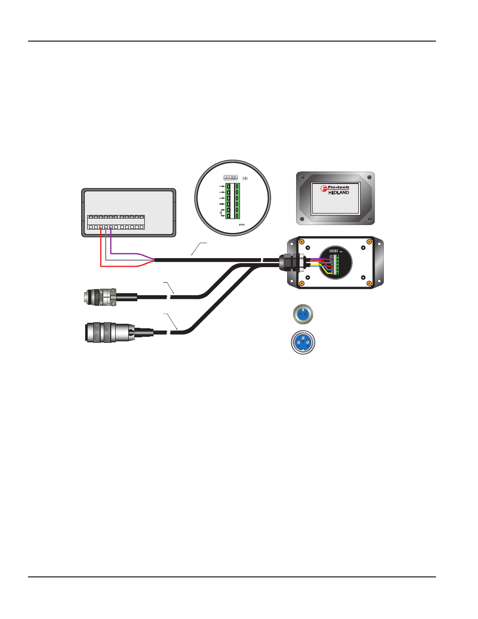
WIRING THE F6600 / F6650 SERIES DISPLAYS
(WITH F5140 K-FACTOR SCALER)
The Flo-tech FSC-375, F6202-F, and F6222-F turbines require the F5140 K-Factor Scaler to amplify the millivolt sensor output for transmission
to the F6600 series display. The turbines produce a low level signal so it is important to keep the F5140 K-Factor Scaler as close to the flow
sensor as possible. Close proximity will minimize signal interference and help eliminate erratic readings.
1. Feed the terminal end of the F2832 or F6234 cable through the wire bushing on the F5140. Insert the three-wire (customer supplied)
cable that will be used to bring power and return the output signal to the F6600 series readout. Tighten the wiring bushing.
2. Connect the BLUE wire from the F2832 or the RED wire from the F6234 cable to terminal 5 of the F5140 K-Factor Scaler. Connect the
YELLOW wire from the F2832 or the BLACK wire from the F6234 cable to terminal 6 of the F5140 K-Factor Scaler. See
Output
Common
+ 12 VDC
3 Wire Cable
(Customer Supplied)
1
2
3
4
5
6
- OUTPUT
+ OUTPUT
- VIN
+ VIN
8.5 - 30 VDC
TURBINE
PICK UP
INTERNAL
3.6K PULL-UP
RESISTOR
JUMPER
PROGRAMMING
PORT
K-FACTOR SCALER
INPUT 8.5 - 30 VDC
MAX INPUT CURRENT: 18 mA
CABLE ASSEMBLY
F6234-6 6 ft (1.8 m)
F6234-15 15 ft. (4.6 m)
CABLE ASSEMBLY
F2832-6 6 ft (1.8 m)
F2832-15 15 ft (4.6 m)
by
®
K-FACTOR SCALER
F5140
S.N. 12345
2200 South Street Racine, WI 53404 U.S.A.
Phone: 262-639-6770 Fax: 262-639-2267
www.hedland.com
F6600 / F6650
Series Display
COMM
INPUT A.
INPUT B
1 2 3 4 5 6
7 8 9 10 11
+12 VDC
1
2
3
4
5
6
Top of
F6234 Cable
3
2
1
1 - N/C (WHITE)
2 - - (BLACK)
3 - + (RED)
Top of
F2832 Cable
A - + (BLUE)
B - - (YELLOW)
B A
Figure 2: Flo-tech frequency output wiring using F5140 K-factor scaler
4. Connect one of the wires from the customer-supplied cable to terminal 4 (+VIN) of the F5140 and note the wire color. Connect the other
end of this wire to terminal 3 (+12V DC) of the F6600 series display.
5. Connect one of the wires from the customer-supplied cable to terminal 2 (+OUTPUT) of the F5140 and note the wire color. Connect the
other end of this wire to terminal 5 (INPUT A) of the F6600 series display.
6. Connect the remaining wire from the customer-supplied cable to terminal 1 (-OUTPUT) of the F5140. Connect the other end of this wire
to terminal 4 (COMM) of the F6600 series display.
NOTE:
N
A jumper wire is required between terminals 1 and 3 of the F5140.
Signal Wiring, F6600 / F6650 and F6700 / F6750 Series Displays
Page 2
June 2014
SGN-UM-00979-EN-06