Programming, Operation, Requirements – Badger Meter Converters User Manual
Page 3: 95 or newer operating system • dc power supply
Operation
OPERATION
Once power is applied, the converter outputs an analog value representative of the measured frequency from the turbine meter.
See
—whichever corresponds to the converter that you have selected for your application.
3
2
1
4
5
(BLACK) - Loop
(WHITE) N.C.
(RED) + Loop
3
4
5
2
1
CABLE
CONNECTOR
CONVERTER
MALE CONNECTOR
+ 4…20 mA
- 4…20 mA
+ 4…20 mA (Sink)
- 4…20 mA (Source)
N.C.
N.C.
N.C.
PIN 3
PIN 4
PIN 5
PIN 2
PIN 1
No Connection
RED
BLACK
WHITE
B220952-15 15 FT.
CABLE ASSEMBLY
B220952-6 6 FT.
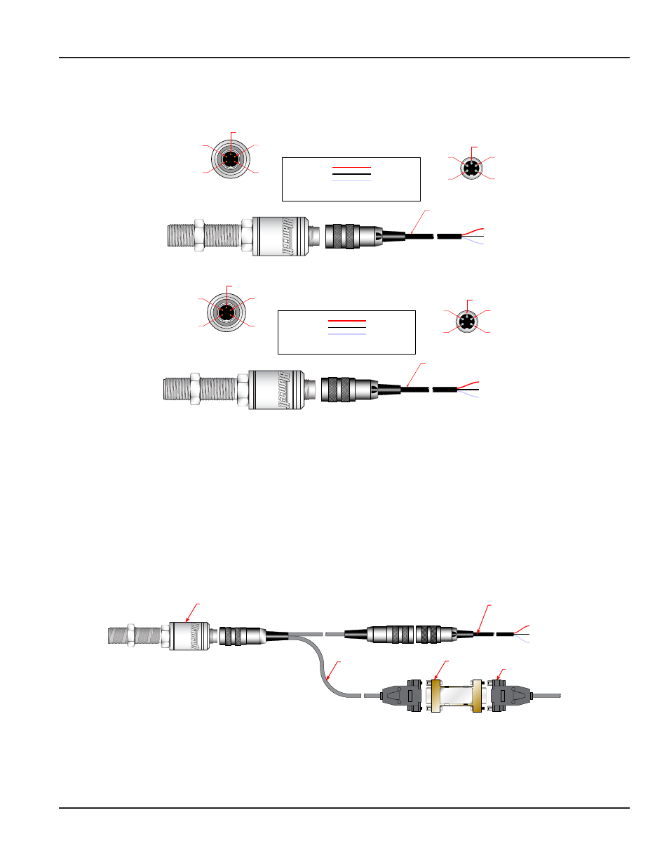
Figure 6: Frequency to current output wiring
(BLACK) SIGNAL
(WHITE) 0V
(RED) 10…30V DC
B220952-15 15 FT.
CABLE ASSEMBLY
B220952-6 6 FT.
3
4
5
2
1
2
1
4
5
3
CABLE
CONNECTOR
CONVERTER
MALE CONNECTOR
10…30V DC
SIGNAL
10…30V DC
SIGNAL
GND
N.C.
N.C.
PIN 3
PIN 4
PIN 5
PIN 2
PIN 1
0 V
RED
BLACK
WHITE
Figure 7: Frequency to Voltage output wiring
OTEE:
N
If your active sensor was purchased with a Blancett turbine meter, the two components ship from the factory calibrated as
a set. If the active sensor is a replacement, the turbine’s K factor has changed, or the sensor is being used with some other
pulse-generating device, programming is necessary.
PROGRAMMING
OTEE:
N
For complete instructions on programming the Blancett intelligent converters see the IFC Programming Manual.
Requirements
•
Sensor/Transducer IFC programming kit PN B220-953
•
RS232 cable (connects programming cable to PC)
•
IBM Compatible PC running Windows
®
95 or newer operating system
•
DC Power Supply
Cable Assembly
Blancett P.N. 6558
Active Sensor
RS
-232
TTL
RS-232 T
O TTL
Con
ver
ter
Model 232LPT
TL
TTL to RS232
Converter
Cable To
Computer
(BLACK) SIGNAL
(WHITE) 0V
(RED) 10…28V DC
Cable Assembly
B220952-6 6 ft.
B220952-15 15 ft.
Figure 8: 6558 programming cable connections
OTEE:
N
The TTL-to-RS232 converter may be as shown in
or it may be a black molded model.
Page 3
July 2014
SEN-UM-00084-EN-02