Connection – Badger Meter Converters User Manual
Page 2
Connection
CONNECTION
The 4…20 mA output can drive auxiliary devices (resistive loads) such as displays, recorders and computers, provided the voltage supplied
by the power source is adequate. Devices must be wired in series with the F-to-I converter and power supply. The voltage drop across the
load(s) and the 6V DC minimum needed to drive the F-to-I converter determine the minimum voltage required from the power supply.
The F-to-I converter acts as a current controlling device. Thus, the current output remains the same even if the power supply voltage
fluctuates or the load resistance changes. The current varies only with respect to the flow rate from the turbine flow meter, as long as the
voltage drop across the F-to-I converter is at least 6V DC.
The load(s) in the circuit generally have some electrical resistance, 100 Ohms for this example. The 4…20 mA loop current produces a
Voltage drop across each load. The maximum Voltage drop across a load(s) exists when the loop current is 20 mA. The power supply must
provide enough Voltage for the load(s) plus the 6V DC minimum insertion loss of the F-to-I converter.
shows a graphical representation of the allowable loads for a given power supply voltage.
F
to
I
Converter
24V DC
Power
Supply
4…20 mA
150
Ohms
100
Ohms
50
Ohms
Total load resistance = 300 Ohms
Total current loop current = 20 mA
300 Ohms x 20 mA = 6000 mV = 6 Volts
The total voltage drop across the load is 6 Volts.
F
to
I
Converter
24V DC
Power
Supply
4…20 mA
1000
Ohms
Total load resistance = 1000 Ohms
Total current loop current = 20 mA
1000 Ohms x 20 mA = 20,000 mV = 20 Volts
The total voltage drop across the load is 20 Volts
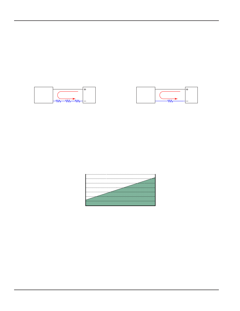
Figure 3: Example 1—Sufficient power supply Voltage
Figure 4: Example 2—Insufficient power supply Voltage
Example 1 shows an installation where the available voltage from the power supply is sufficient to accommodate
a 6 Volt drop. Subtract 6 Volts from the 24 Volt source to determine that 18 Volts are available to power the F-to-I converter. The 18 Volts is
within the specified 10…30 Volt range and is sufficient to power the F-to-I converter.
Example 2 shows an installation where the available voltage from the power supply is not sufficient to accommodate a
20 Volt drop. Subtract 20 Volts from the 24 Volt source to determine that 4 Volts is available to power the F-to-I converter. The 4 Volts is
below the specified 10…30 Volt range so is not adequate to power the F-to-I converter. If for example, the power supply voltage was 30
Volts instead of 24 Volts, the Voltage available to power the F-to-I converter would be 10 Volts and within the specified range.
200
400
600
800
1000
1200
1400
10
12
14
16
18
20
22
24
Supply Voltage (VDC)
Loop Load (Ohm's)
Operate in the
Shaded Region
26
28
30
Figure 5: Allowable loop resistance chart
Page 2
July 2014
SEN-UM-00084-EN-02