Part number information, Attention, New turbine kit installation mportant i – Badger Meter 1100 User Manual
Page 10
Turbine Flow Meter, 1100 Series
New Turbine Kit Installation
MPORTANT
I
Before reassembly, note that an arrow is cast or engraved on each component. The arrow indicates the primary flow direction. When
reassembled, the arrowheads must point in the direction of the fluid flow. The arrows must also be oriented in the up position on
both rotor supports. The magnetic pickup side of the body signifies the up position. Performance of repair kit calibration is in the up
position. Reinstallation of the repair kit in the up position ensures continuation of accurate measurements.
, and
show the proper alignment and orientation of the repair kits.
OTEE:
N
Fractional size (3/8 in ., 1/2 in . and 3/4 in .) rotors do not contain a cast or engraved arrow . However, a colored cap
on the downstream side of the rotor shaft indicates flow direction . Remove this cap before assembly, noting
flow direction .
1 . Install one of the rotor supports into the body bore, noting the orientation of the arrow .
2 . Secure a retaining ring in the groove provided . Check for complete installation of retaining rings in each groove .
OTEE:
N
4 in . and larger meters have a retaining ring at both ends of the rotor (see
) .
3 . Insert the rotor and second rotor support in the opposite side of the body, noting the orientation of the arrow .
4 . Secure the second retaining ring in the opposite groove, using the same procedure as in step 2 above .
EXCESS AIR PRESSURE MAY DAMAGE THE ROTOR AND BEARINGS BY OVER SPINNING.
ATTENTION
LA PRESSION ATMOSPHÉRIQUE EXCESSIVE PEUT ENDOMMAGER LE ROTOR ET LES ROULEMENTS PRÈS AU-DESSUS DE
LA ROTATION.
5 . Check the meter by lightly puffing air through the assembly . If the rotor does not turn freely, disassemble the meter and
remove anything that might obstruct movement of the rotor .
OTEE:
N
At this time, electronics require recalibration . Refer to the display's user manual . If there are any questions on
recalibration, contact Badger Meter, Inc . or the manufacturer of the associated electronics .
6 . Install the magnetic pickup .
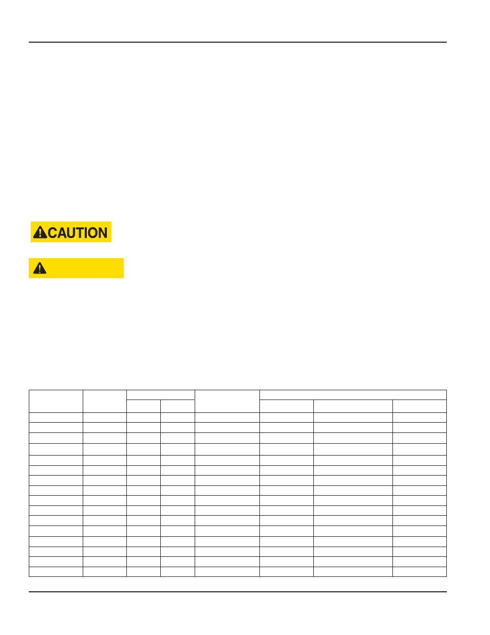
PART NUMBER INFORMATION
Part Number
Meter Size
End to End Length
End Connection
Flow Ranges
inches
mm
gpm
bpd
m³/d
B110-375-1/2
3/8 in .
3
76 .2
1/2 in . Male NPT
0 .6…3 .0
20…100
3 .3…16
B110-500-1/2
1/2 in .
3
76 .2
1/2 in . Male NPT
0 .75…7 .5
25…250
4 .1…41
B110-750-1/2
3/4 in .
3
76 .2
1/2 in . Male NPT
2…15
68…515
10 .9…81 .75
B110-375
3/8 in .
4
101 .6
1 in . Male NPT
0 .6…3 .0
20…100
3 .3…16
B110-500
1/2 in .
4
101 .6
1 in . Male NPT
0 .75…7 .5
25…250
4 .1…41
B110-750
3/4 in .
4
101 .6
1 in . Male NPT
2…15
68…515
10 .9…81 .75
B110-875
7/8 in .
4
101 .6
1 in . Male NPT
3…30
100…1000
16…160
B111-110
1 in .
4
101 .6
1 in . Male NPT
5…50
170…1700
27 .25…272 .5
B111-115
1-1/2 in .
6
152 .4
1-1/2 in . Male NPT
15…180
515…6000
82…981
B111-121
2 in . Low
6
152 .4
2 in . Male NPT
15…180
515…6000
82…981
B111-120
2 in .
10
254
2 in . Female NPT
40…400
1300…13,000
218…2180
B111-130
3 in .
12-1/2
317 .5
3 in . Grooved End
60…600
2100…21,000
327…3270
B111-140
4 in .
12
304 .8
4 in . Grooved End
100…1200
3400…41,000
545…6540
B111-160
6 in .
12
304 .8
6 in . Grooved End
200…2500
6800…86,000
1090…13,626
B111-180
8 in .
12
304 .8
8 in . Grooved End
350…3500
12,000…120,000
1363…19,076
B111-200
10 in .
12
304 .8
10 in . Grooved End
500…5000
17,000…171,000
2725…27,252
Page 10
July 2014