14 wiring connections 2.6 – West Control Solutions MRC 7000 Controller Manual User Manual
Page 14
14
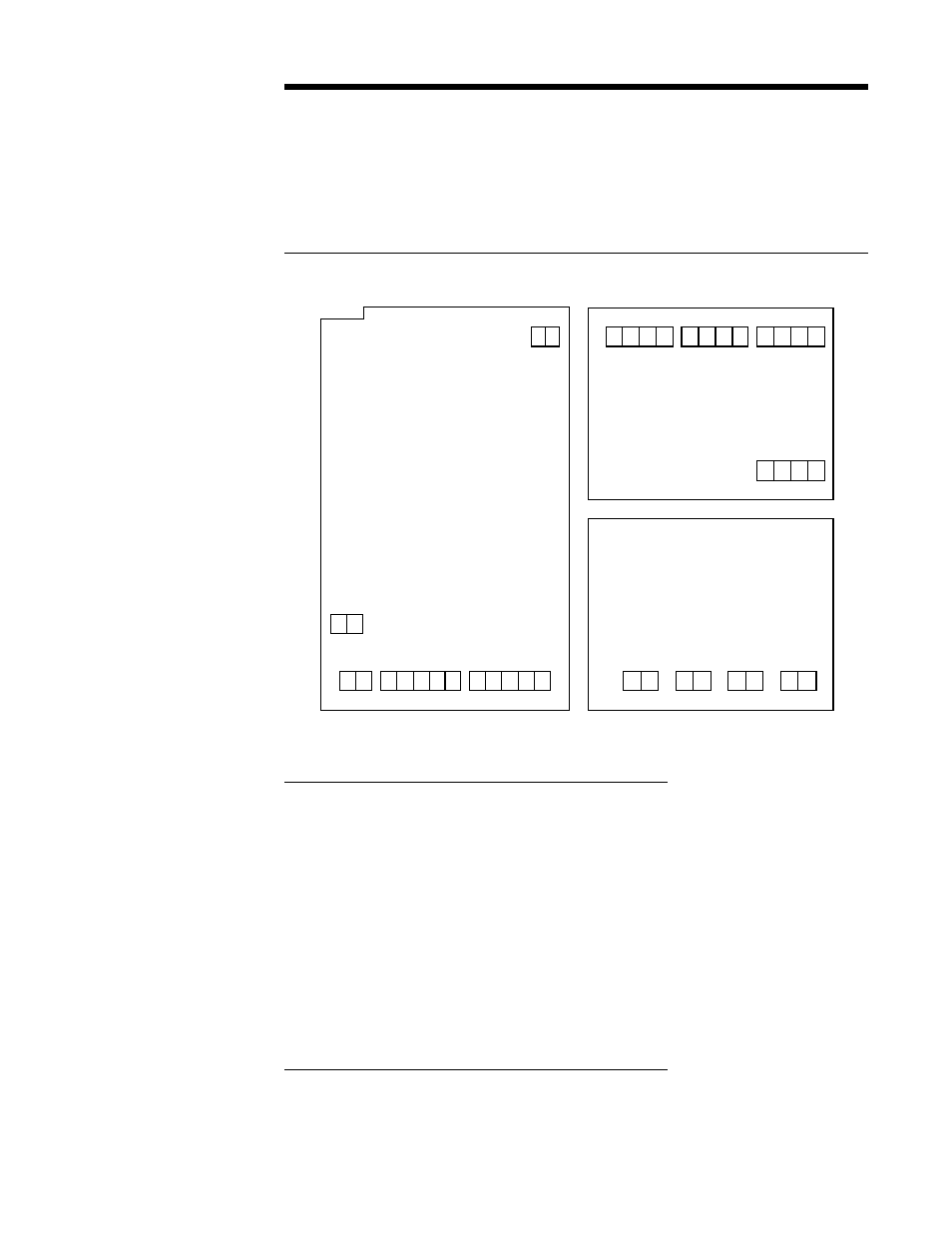
Wiring Connections 2.6
All wiring connections are typically made to the instrument at the time of installation. Connec-
tions are made at the terminal boards provided, two 12 gauge wires maximum. Terminal
boards are designated TB1 through TB13. See Figure 2-4 for the terminal board locations.
The number of terminal boards present on the instrument depend upon the model number/
hardware configuration.
FIGURE 2-4
2.6.1 ELECTRICAL CONDUIT OPENINGS
The instrument case will have 3 or 4 conduit openings, depending upon the number of outputs
specified. To help minimize electrical noise that may adversely affect the operation of the
instrument the wires indicated below should be routed through the conduit opening specified.
See Figure 2-1 (page 9) for conduit opening locations.
EC1-
AC Power Input
EC2-
Analog input and mADC outputs
EC3-
SPST relay or SSR driver outputs
EC4-
SPST relay or SSR driver outputs (provided when > 4 relays & SSR drivers total are
specified)
Unused conduit openings should be sealed.
2.6.2 AC POWER WIRING CONNECTIONS
WARNING: Avoid electrical shock. AC power wiring must not be connected at the source
distribution panel until all wiring connections are completed.
TB3
TB4
TB5
TB1
1 2
1 2 1 2 3 4 5 1 2 3 4 5
1 2 3 4 1 2 3 4 1 2 3 4
TB6
TB7
TB8
TB9
1 2 3 4
RELAY/SSR Driver
Board
TB10
TB11
TB12
TB13
1 2
1 2 1 2 1 2
Current Output Board
Processor Board
TB 2
1 2