Actuators and accessories, Valve identification – Warren Controls 1800 Series Heavy Globe Control Valves User Manual
Page 2
2
2600 Emrick Blvd • Bethlehem, PA 18020 • USA •800-922-0085 • www.warrencontrols.com
equipment into the overall plant operational procedures. Warren
Controls does not assume responsibility for the selection, use, or
maintenance of any product. Responsibility for proper selection,
use, and maintenance of any Warren Controls product remains
solely with the purchaser and end-user
actuators anD accessorIes
Series 1800 Heavy Globe Control Valves are available with
a variety of actuators and accessories. These actuators and
accessories have separate instructions. For complete control
valve installation, operation, and maintenance instructions see
also the instructions for the actuator and accessories in use.
valve IDentIfIcatIon
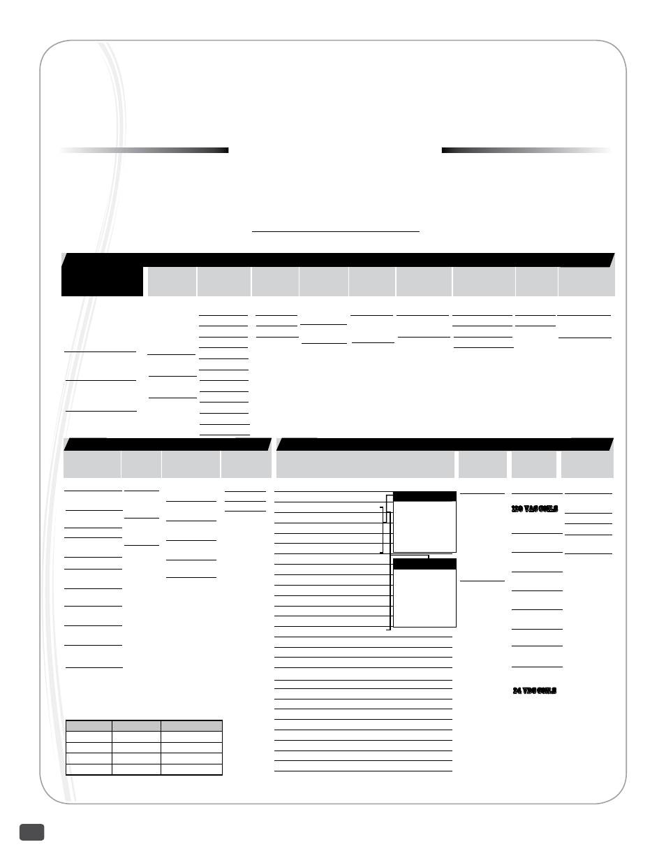
To use these instructions it is necessary to identify the configuration of the valve. Factory assembled control valves have a
nameplate mounted on the actuator. The valve’s part number (P/N) is present on the plate. The part number represents the
configuration of the control valve. To identify the valve’s type, size, actuator, accessories, and other characteristics decode the
part number using configuration table. If the information is incomplete, incorrect, or not present contact the factory with the
valve serial number listed on the plate. (See Information Present on Control Valves section for location of part number, serial
number, and other important information on valve.)
Valve
Type
Size
Body
Material
End
Connection
Trim Style Trim Material Trim Cv
40
2-Way,
Single Seat
43
2-Way
Cage-
Balanced
50
3-Way
Mixing
52
3-Way
Diverting
050
1/2 inch
075
3/4 inch
100
1 inch
150
1-1/2 inch
200
2 inch
250
2-1/2 inch
300
3 inch
400
4 inch
600
6 inch
800
8 inch
010
10 inch
012
12 inch
W
WCB
F
CF8M
R
Cast Iron
F
125/150 lb.
Flanged
G
250/300 lb.
Flanged
F
Full Port
1
1st Port Reduction
2
2nd Port Reduction
3
3rd Port Reduction
Model
Packing
Type
T
Teflon
G
Graphite
18H
2” - 4” Bodies
Diaphragm:
84” or 115”
Cylinder: 6”
or 8”
18J
6” - 12” Bodies
Diaphragm: 115”
Cylinder: 8” or 12”
18K
1/2” - 1 1/2”
Bodies
Diaphragm: 84”
E
Equal %
L
Linear
Types
50/52
Linear only
S
316 SS
6
Alloy 6
Wrapped
Bonnet
Construction
S
450 Tmax
x
800F Tmax
w/Ext. Bonnet
V A L V E B O D Y
0000
None
PoSITIoNERS:
BxP_ BLX Pneumatic
BxE_ BLX ElectroPneumatic
BxI_ BLX ElectroPneu. Intrn. Safe
BxX_ BLX ElectroPneu. Exp. Proof
BxF_ BLX ElectroPneu. Fail Freeze
76P_ Moore760 Pneumatic
76E_ Moore760 Electro-Pneumatic
P24_ Siemens PS2 Electro-Pneumatic
P2H Siemens PS2 2,3,4 Wire HART
P2P_ Siemens PS2 PRoFIBUS PA
P2F_ Siemens PS2 FoUND. FIELDBUS
PRoXIMITY SWITCHES:
PX11 Mark 1 Series - 2 ea. SPDT
PX12 Mark 1 Series - 2 ea. SPDT w/2k Pot.
PX13 Mark 1 Series - 2 ea. SPDT w/4-20 Feedback
PX14 Mark 1 Series - 4 ea. SPDT
PX15 Mark 1 Series - 6 ea. SPDT
I/P’s Use with Diaphragm only
MAP1 Type 500X I/P, 3-9 PSI
MAP2 Type 500X I/P, 9-15 PSI
MAP3 Type 500X I/P, 3-15 PSI
MAP4 Type 500X I/P, 1-17 PSI
MAP5 Type 500X I/P, 6-30 PSI
MAP6 Type 550X I/P, 0-30 PSI
MAP7 Type 550X I/P, 0-60 PSI - For 15 or 5X only
MAP9 Type 950X I/P, 3-15 EXP
Actuator
Series
Action
Spring Range Handwheel Positioners, I/P’s & Limit Switches
Air Filter
Regulators
Special
options
ASCo
Solenoids
0 None
R Reverse
Stem
Fail Down
D Direct
Stem
Fail Up
00 None
DIAPHRAGMS:
84 DL84
(84 Sq.In.)
8X DL84XR
15 DL115
(115 Sq.In.)
5X DL115XR
CYLINDERS:
C2 6” Spring Fail
(for 18H)
C3 8” Spring Fail
(for 18H)
C4 8” Spring Fail
(for 18J)
C5 12” Spring
Fail
(for 18J)
0 None or
Cylinder
L Low
3-9psi R/D
F Full
3-15psi
R/D
H High
9-15 psi R/D
X Xtra-High
DL115XR
0 None
R Reverse
D Direct
0
None
A
Type 300,
0-30 PSI,
B
Type 300,
0-60 PSI
C
Type 300,
0-120 PSI,
D
Type 350SS,
0-100 PSI
0
None
S
Special opts
or Set-up
T
SS Tubing
G
SS Tagging
B
SS Tubing
and Tagging
A C C E S S O R I E S
0
None
120
VAC COILS
A
8320G184
3-Way Brass
B
8320G202
3-Way SS
J
8342G1
4-Way Brass
K
8342G701
4-Way SS
L
EF8320G184
3-Way EXP Br.
M
EF8320G202
3-Way EXP SS
V
EF8342G1
4-Way
EXP
Br.
W
EF8342G701
4-Way EXP SS
24
Vdc COILS
Z
8320G184
3-Way Brass
FAILURE MoDES:
MODE
VALVE TYPE
ACTUATOR ACTION
Closed 40/43 Reverse
open 40/43 Direct
Upper Closed*
50/52
Direct
Upper open
50/52
Reverse
*Standard
0 No Additions
L w/Mech. Lmt Swtch’s
F w/4-20 Feedback
B w/Swtch’s &
Feedback
NoTE:
L,F,B not available
4th digit spec.
F Full Range Signal,
3-15 PSI or 4-20mA
L Low of Split Range,
3-9 PSI or 4-12mA
H High of Split Range,
9-15 PSI or 12-20mA
x
digit spec.
A C T U A T O R