Vms-35, Vms-35 wiring diagram, Vms-35 bcm – Warren Controls E030 Electric Actuator User Manual
Page 5: Specifications, No tes
5
BAC_IOM_RevA_0214
Actuator Usage:
E030 (E030 includes a VMS-35 BCM), E029, E024
Power supply:
24 VAC ± 20% 50/60 Hz
Power Consumption: 40 VA (add VA rating for actuator used)
Number Actuators:
One or Two
Construction:
Battery w/Circuit Board, Charger and Transformer
Enclosure Type:
NEMA 4X, IP66, UL 4X, CSA 4X
Flame Retardant:
UL 50
Construction:
UV Stabilized Fiberglass Reinforced Polyester,
Polycarbonate Hinge and Closed Cell Neoprene Gasket
Connections:
Two 1/2 IN conduit with one plug
Number Batteries: One
Initial Charge:
2-4 hours
Battery Life:
Up to 5 years … Replacement battery
model UB1213 / 12V, 1.3 Ah
Mounting:
Feet for Wall Mount (4.91” x 8.75” centers)
Environmental:
Operating/ Storage:
Ambient +32°F to +104°F
(0 to +40°C) – due to battery
Weight:
4.25 lbs (2 kg)
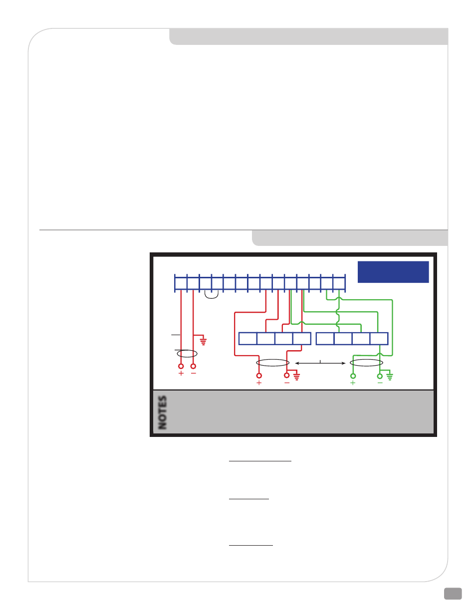
VMS-35 WIRING DIAGRAM
TERMINALS
L
System Power 24 VAC (+)
LN
System Neutral (-)
RC
Remote Control
BT
Battery Test (+)
TG
Test Ground (-)
C1
Control Signal 1st Actuator (+)
C2
Control Signal 2nd Actuator (+)
NC1
Not Used
NC2
Not Used
NO1
Relay Normally Open 1st Actuator
NO2
Relay Normally Open 2nd Actuator
AC
24 VAC Out (+)
Power Failure: Terminal AC changes to 24 V square wave from battery/
inverter. A relay breaks the connection between Terminals C1 and NO1
forcing the actuator to return to the rotation switch position (See page
11 for explanation of rotation switch position).
Loss of Signal: Terminal AC uses 24VAC building power. The control
signal is broken forcing the actuator to return to the rotation switch
position (See page 11 for explanation of rotation switch position).
Operation:
Proportional Normal: Terminal L is connected to 24 VAC building
power. Terminal LN completes the circuit to BK. Actuator responds to
modulating input signal.
VMS-35 BCM
(BACK-UP CONTROL MODULE)
SPECIFICATIONS
Power
24 VAC
HOT
Existing Jumper
L
LN RC LN TG BT
AC LN
NC1
C1 NO1
NC2
C2 NO2
CONTROL SIGNAL (S)
(RECOMMENDED)
(RECOMMENDED)
OUTPUT TO
ACTUATOR A
OUTPUT TO
ACTUATOR B
(IF USED)
Actuator B
Actuator A
1. The VMS-35 can power one (1) or two (2) actuators.
2. Energize 24 VAC before connecting red lead to battery.
3. Also read actuator wiring and setup instructions.
4. To prevent signal interference proper signal wire cable
shielding is recommended.
5. When using long wire runs and a 2 – 10 Vdc signal,
signal and power cables should be run in separate
conduits to avoid interference.
NO
TES
VMS-35
OR#5(U) WH#3(Y) RD#2(+) BK#1(-)
OR#5(U) WH#3(Y) RD#2(+) BK#1(-)