Hardware setup – Asus INTEL CUW(E)-FX User Manual
Page 37
37
3. HARDWARE SETUP
Connectors
3. H/W SETUP
ASUS CUW(E)-FX User’s Manual
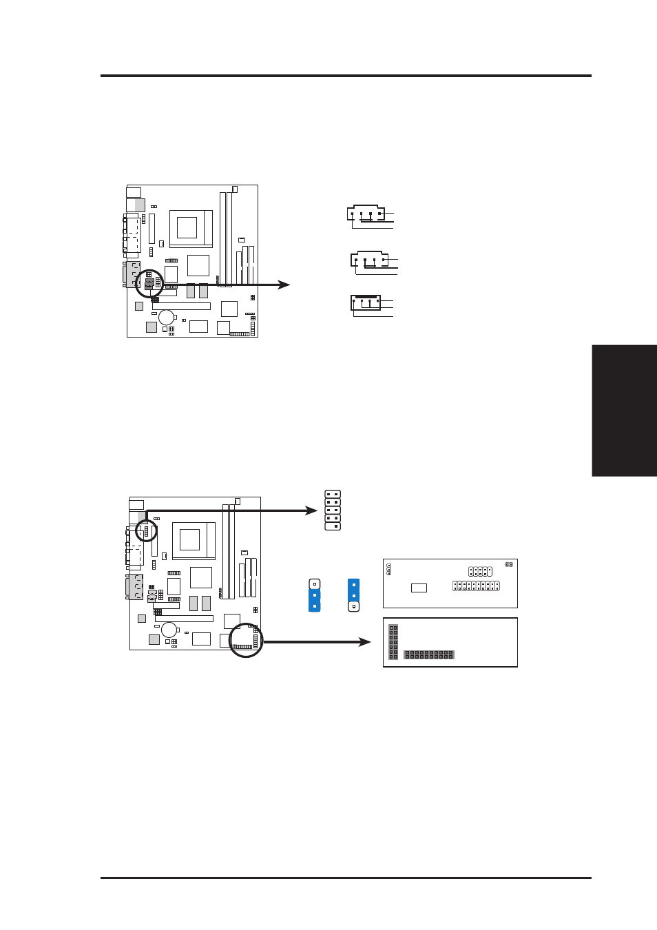
21) Internal Audio Connectors (4-pin VIDEO, CD1, MODEM)
These connectors allow you to receive stereo audio input from such sound sources
as a CD-ROM, TV tuner, or MPEG card. The MODEM connector allows the
onboard audio to interface with a voice modem card with a similar connector. It
also allows the sharing of mono_in (such as a phone) and mono_out (such as a
speaker) between the onboard audio and the voice modem card
®
CUW(E)-FX
CUW(E)-FX Internal Audio Connectors
MODEM
Modem-Out (from Modem)
Ground
Modem-In (to Modem)
CD1 (Black)
Right Audio Channel
Left Audio Channel
Ground
VIDEO (Green)
Right Audio Channel
Left Audio Channel
Ground
22) Front Panel USB Header (10-1 pin FRONTUSB)
If you do not want to use the USB ports on the back panel, a USB header is
available midboard. Connect an external connector set to the 10-1 pin block and
mount it to the front panel. NOTE: The back and front panel ports cannot be
used at the same time.
CUW(E)-FX Front Panel USB
and USB Hub Headers
®
CUW(E)-FX
1: USB Power
2: USBP2–
3: USBP2+
4: GND
5: NC
6: USB Power
7: USBP3–
8: USBP3+
9: GND
Back View
Front View
USBPWR
FRONTUSB
PANEL
IDELED
USB Hub Module
1
2
3
1
2
3
+5V
(Default)
+5VSB
USBPWR
FRONTUSB
1
5
6
10
USB Hub
Chip
If you need additional USB ports, an optional USB hub module is available.
Remove the jumpers on the VPANEL connector and connect the module di-
rectly to the PANEL and VPANEL connectors. You can then connect an exter-
nal connector set to the USB Hub header and mount it to either the front or back
panel for a total of four USB ports.