SHIMPO TT-Series User Manual
Page 5
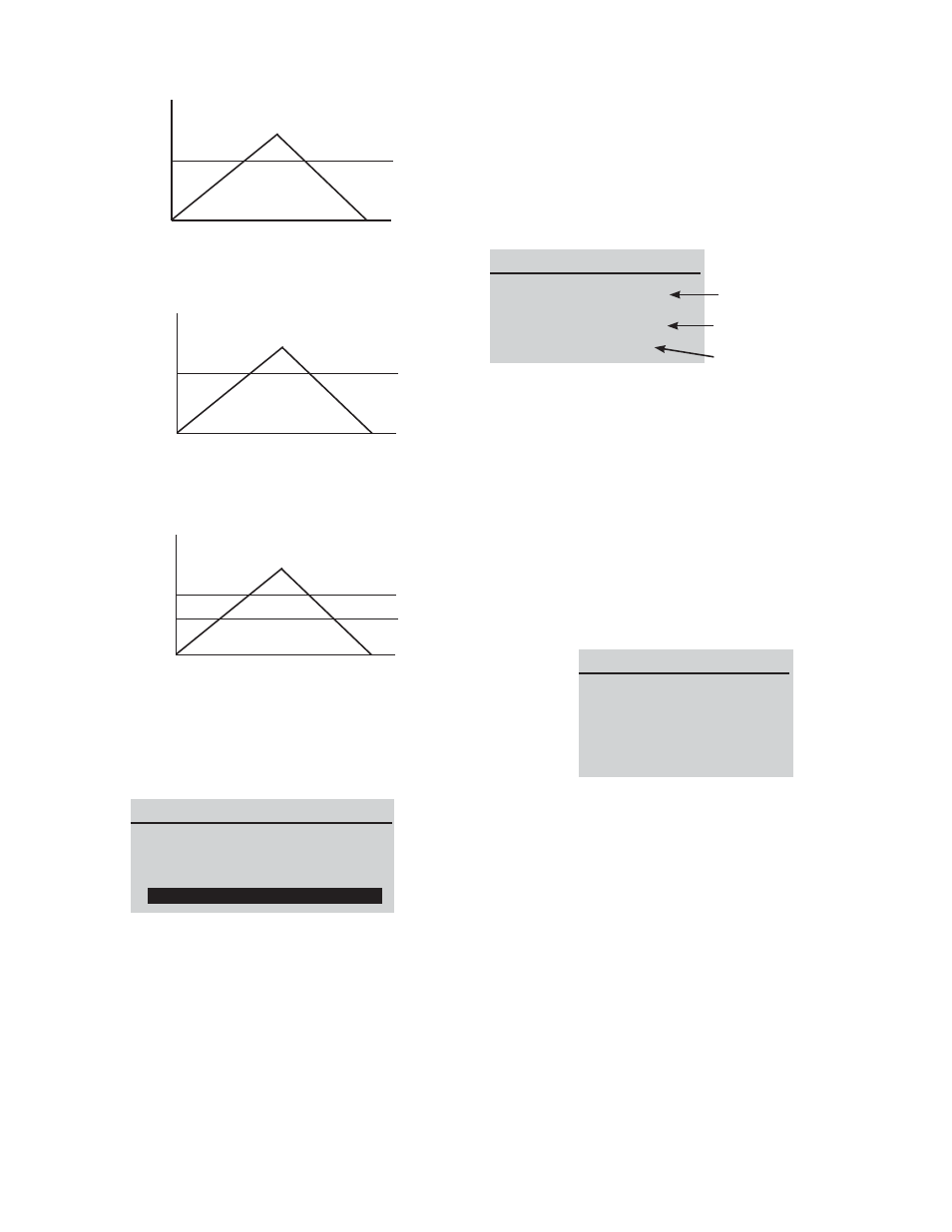
Example: LOWER LEVEL = 0 N.m, UPPER LEVEL = 20 N.m
Figure 6a
Example: LOWER LEVEL = 20 N.m, UPPER LEVEL = 0 N.m
Figure 6b
Example: LOWER LEVEL = 10 N.m, UPPER LEVEL = 20 N.m
Figure 6c
2) MEMORY: The TT offers the ability to view saved records, de-
lete last or delete all records. It can also upload the data if con-
nected to a PC. To access, in the menu list highlight Memory and
press ENTER.
Figure 7: Memory Menu
In the VIEW sub-menu, Press UP and DOWN to scroll through the
list of values. Press and hold to scroll through more quickly.
Select 2) Delete Last and press ENTER. Choose Yes and the
tester will delete the last saved record and return to the Memory
menu. If you selected 3) Delete All and press ENTER, choose Yes
to remove all stored records. The unit will automatically return to
the memory menu after the selection.
To upload all the values to the PC software program, highlight
UPLOAD ALL and press the ENTER key.
3) CALIBRATION: The calibration feature is used by service tech-
nicians for calibrating the tester. Proper equipment is required to
perform this task. Contact Nidec-Shimpo or your dealer for ad-
ditional details.
4) DIAGNOSTIC: This diagnostic feature is used to check status
of the load cell. If you suspect that your load cell transducer has
sustained an overload, it is possible to check the status. Place the
tester horizontally on the flat level surface and select “DIAGNOS-
TIC” in the main menu.
Figure 8: Diagnostic Menu
If the % offset is between 5% - 10 % please contact Nidec-Shimpo
or your supplier to arrange for a proper calibration.
If the % offset is greater than 10% the unit is possibly damaged
and needs repair or replacement.
These values are given as an indication only. The need for calibra-
tion or repair may vary according to the individual characteristics
of the load cell.
5) ABOUT: The ABOUT sub-menu displays the information of
your unit such as Firmware revision, Model, Capacity and Serial
number.
Figure 9: About Menu
MOUNTING: For proper operation and safety, it is necessary to
mount the torque tester with ranges of 25 N-m and higher. Fasten
the integral mounting bracket properly with 4 bolts and nuts to a
secure work surface. Mounting may be vertical or horizontal. For
lower torque ranges, this mounting bracket adapter is available
as an accessory if securing to a work surface is desired. To install
the bracket to the back of the unit, remove the four outer screws
with rubber feet. Disguard the rubber feet. Line up the adapter
plate’s four holes with the four outer threaded inserts on the bot-
tom of the TT. Attach the adapter bracket with the four screws that
were previously removed. Tighten securely. Line up the adapter
plate’s four holes with the four outer threaded inserts on the bot-
tom of the TT.
5
Load
Time
“UPPER” LED on
“OK” LED on
Upper Level
Load
Time
“OK” LED on
“LOWER” LED on
Lower Level
Load
Time
“UPPER” LED on
“LOWER” LED on
Lower Level
Upper Level
“OK” LED on
MEMORY MENU
1) VIEW
2) DELETE LAST
3) DELETE ALL
4) UPLOAD ALL
DIAGNOSTIC
OVERLOAD COUNT: 2
ORG. OFFSET: +0.4%
CUR. OFFSET: +0.4%
A total of overload count
% offset from the
prior calibration
Current % offset
ABOUT
FIRMWARE REV.: 1.00
MODEL: TT
CAPACITY: 10 N.M
S/N: 05130001