Configurable parameters, 7 maintenance, 8 troubleshooting – Pyromation Series 442 User Manual
Page 9
Copyright 2006 Pyromation, Inc., All rights reserved.
9 of 11
Phone (260) 484-2580
•
FAX (260) 482-6805 or (800) 837-6805
•
www.pyromation.com
442-D
6.7 Configuration using HART
protocol and TransComm
The configuration of the head transmitter can be done using both the HART
protocol and the TransComm software. The following
table shows the structure of the interactive menu led operation of TransComm.
Configurable parameters
Standard settings
• Sensor type
• Connection mode (2, 3 or 4 wire connection)
• Units (°C or °F)
• Measurement range start (depends on sensor)
• Measurement range end (depends on sensor)
• Coefficient X0 to X4 (on sensor type Polynom RTD/TC)
• Temperature-compensation (on sensor type Polynom TC)
Expanded settings
• Cold junction compensation (internal/external on TC connection)
• Temperature external (on TC with cold junction compensation external)
• Compensation resistance (0 to 20)
Ω on 2 wire connection
• Fault condition reaction (
≤ 3.6 mA or ≥ 21.0 mA)
• Output (analog standard/inverse)
• Damping (0 to 8) s
• Offset (-9.9 to +9.9)
°C [-17.8 to +17.8] °F
• TAG (Measurement point identification)
• Identifier (Descriptor)
Service functions
• Simulation (on/off)
For detailed TransComm operating instructions please read the online documentation contained in the software.
6.8 Interactive setting up of the temperature transmitter
Customer specific linearization and sensor matching is done using the TransComm configuration software. The program
calculates the linearization coefficients X0 to X4 that need to be entered into the PC configuration software.
7 MAINTENANCE
The head transmitter is maintenance free.
8 TROUBLESHOOTING
Always start troubleshooting with the checklists below if faults occur after start up or during operation. This takes you directly (via
various queries) to the cause of the problem and the appropriate remedial measures. Note: Due to its design, the device cannot
be repaired. However, it is possible to send the device in for examination.
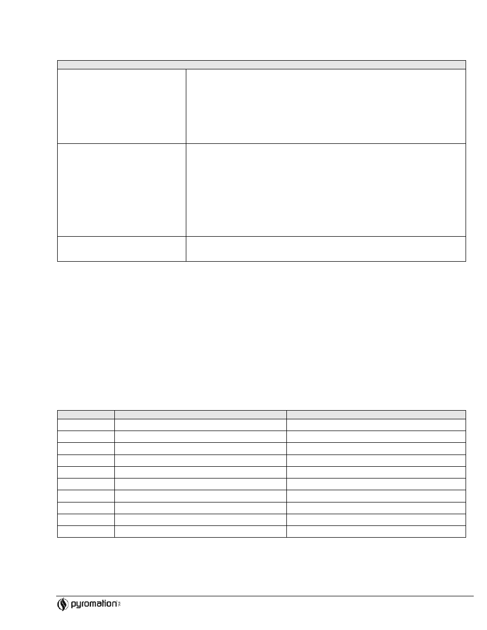
8.1 Application fault message
Application fault messages are shown in the display of the HART
hand operating module “DXR275/375” once the menu point
“ERROR CODE” has been selected.
Fault code
Cause
Action/cure
0
No fault, Warning
None
10
Hardware fault (unit defective)
Replace head transmitter
11
Sensor short circuit
Check sensor
12
Sensor cable open circuit
Check sensor
13
Reference measurement point defective
None
14
Unit not calibrated
Return head transmitter to manufacturer
106
Up/Download active
None (will be automatically acknowledged)
201
Warning: Measured value too small
Enter other values for measured value range start
202
Warning: Measured value too large
Enter other values for measured range end
203
Unit is reset (to factory default settings)
None