5 operation, 6 installing – Pyromation Series 442 User Manual
Page 3
Copyright 2006 Pyromation, Inc., All rights reserved.
3 of 11
Phone (260) 484-2580
•
FAX (260) 482-6805 or (800) 837-6805
•
www.pyromation.com
442-D
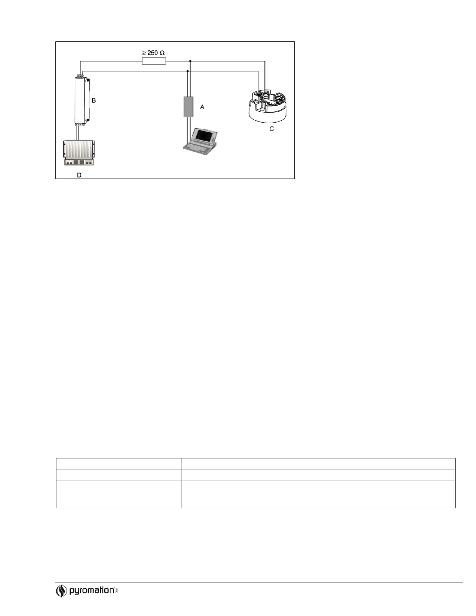
Connection of HART
modem using TransComm Software
Figure 4-3
Electrical connection of the HART
modem
A = HART
modem
B = Loop power supply
C = HART
transmitter
D = PLC with a passive input
4.4 Shield grounding
Please take note when installing the head transmitter remotely in a field housing. The shield on the (4 to 20) mA signal output must
have the same potential as the shield at the sensor connections! When using grounded thermocouples, shielding of the output (4
to 20) mA cable is recommended. In plants with strong electromagnetic fields, shielding of all cables with a low ohm connection to
the transmitter housing is recommended.
5 OPERATION
5.1 Communication
The temperature transmitter is setup using the HART
protocol. The values measured can also be read using the HART
protocol
using a universal hand operating module “HART
Communicator DXR 275/375.
5.2 HART
Communicator DXR 275
Selection of the unit functions using the “HART
Communicator” is done using various menu levels as well as with the help of a
special HART
function matrix (see figure 6-2).
Hint: When using the HART
hand unit all parameters can be read out, however, the programming is blocked. It is possible to
release the HART
function matrix by entering 281 in the LOCK function. The condition remains even after a power failure. The
HART
function matrix can be locked again by releasing the personal code number. More detailed information to the HART
hand
operation module can be found in its respective operating manual.
6 INSTALLING
6.1 Installation check
Monitor all connections making sure they are tight. In order to guarantee fault free operation the terminal screws must be tight onto
the connection leads. The unit is now ready for operation.
6.2 Function check
Measuring the analog (4 to 20) mA output signal or following failure signals:
Underranging
Linear drop from 4.0 to 3.8 mA
Overranging
Linear increase from 20.0 to 20.5 mA
Failure, e.g. sensor breakage; sensor
short circuit
≤ 3.6 mA (“low”) or ≥ 21 mA (“high”), can be selected
The “high” alarm setting can be set between 21.6 mA and 23 mA, thus providing the
flexibility needed to meet the requirements of various control systems.
6.3 Installation
Once the power supply has been connected the head transmitter is operational.