Pyromation Series 442 User Manual
Page 4
Copyright 2006 Pyromation, Inc., All rights reserved.
4 of 11
Phone (260) 484-2580
•
FAX (260) 482-6805 or (800) 837-6805
•
www.pyromation.com
442-D
6.4 Quick Setup
The head transmitter left the factory with a default parameter configuration. If no customer specific configuration was mentioned on
the order then the default parameter configuration is constructed as follows:
Sensor
Pt100 (RTD)
Connection mode
3-wire
Measurement range and units
(0 to 100) °C
Using the Quick Setup the operator is led through all the most important unit functions that must be setup for standard
measurement operation of the unit. Using the HART
hand module a quick set-up of the black highlighted fields of the HART
function matrix (see figure 6-2) is possible.
• Type of sensor
(V2H0)
• Unit meas. Value (V2H2)
• Value of 4 mA
(V2H4)
• Value of 20 mA
(V2H5)
• Connection
(V2H6)
6.5 Configuration with HART
protocol
Selection of all head transmitter functions using the HART
hand module is done with various menu levels with the help of the
Pyromation function matrix (see figure 6-2). All head transmitter functions are described in 6.6, Description of unit functions.
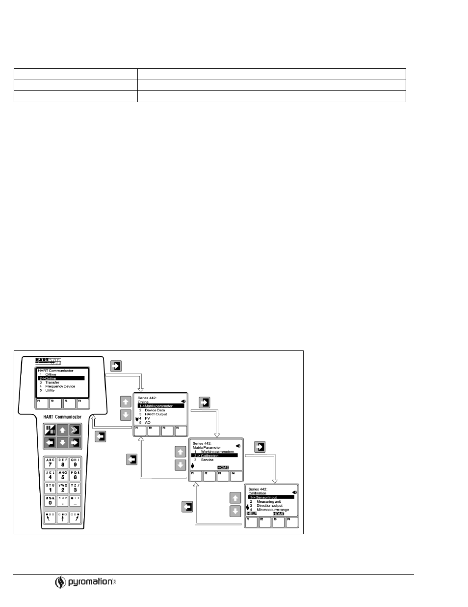
What needs to be done:
1. Switch on the hand module:
- Measurement unit is not yet connected. The HART
main menu appears. This menu level appears for all HART
programming independent of the type of instrumentation. Information to offline programming can be found in the
“Communicator DXR 275/375 operating manual.
- Measuring unit is connected. The menu level “Online” appears. In this “Online” menu level the actual measured data such
as measured value (PV) and output current (AO) are continuously displayed. Entry into the Series 442 operating matrix is
done using the line “Matrix parameters”. This matrix systematically contains all HART
accessible functions.
2. Using “Matrix parameters” the function group can be selected (e.g. basic calibration) and then followed by the required
function, e.g. “Sensor input”.
3. Enter numeric values or change settings. Then acknowledge using the F4 “Entry” function key.
4. “SEND” appears when operating the F2 function key. Once the F2 key has been operated all values entered in the hand
module are transmitted to the Series 442 measurement system.
5. A return to the “Online” menu level is made using the F3 “HOME” function key. Here, the actual transmitter values measured
with the new settings can be read.
Figure 6-1
Configuration at the hand module example “Sensor input”