Precision Control Systems ExtrudeIR 4069E User Manual
Page 15
Model 4069E ExtrudeIR
TM
Instruction Manual
Operating
Instructions
Research, Inc.
Page 11 of 26
Power Wiring Connections
Line Connections
Load Connections
Referring to the wiring specification in Table 3-1, connect the external power lines to
the top of the disconnect switch.
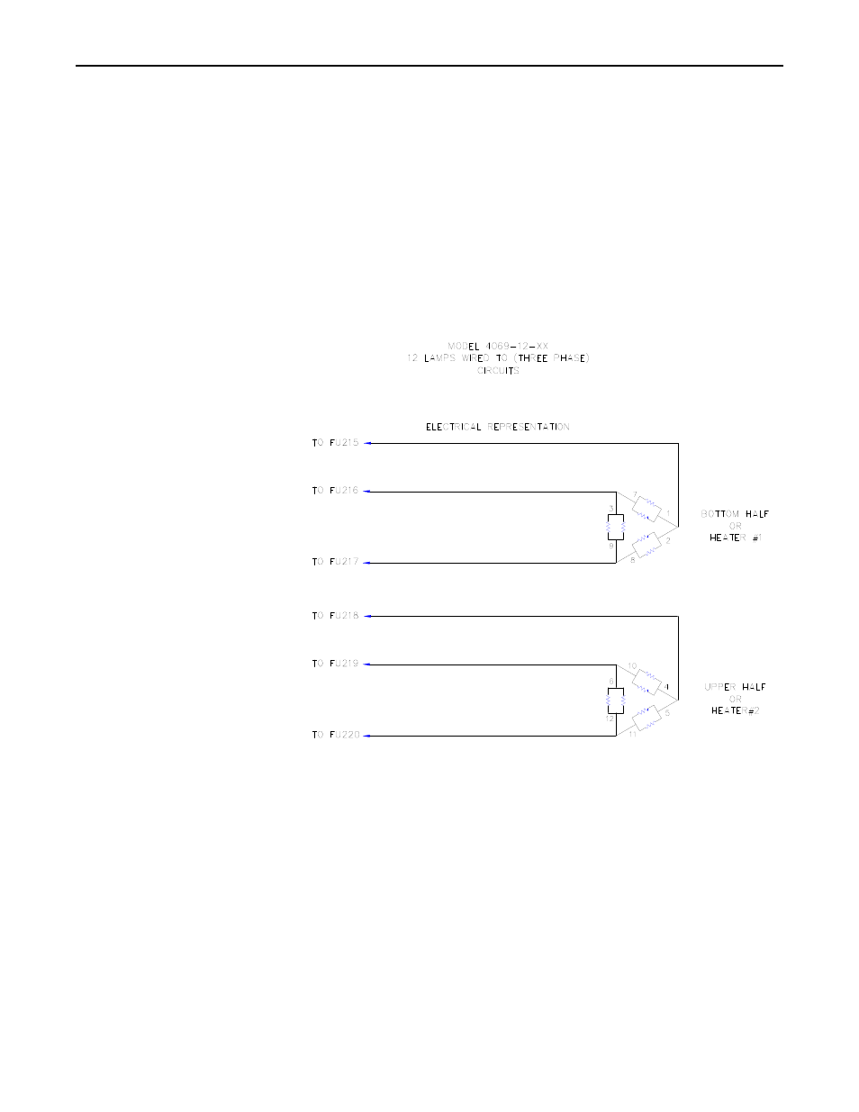
The model 4069E control system has 2 (3-pole) load fuseblocks for distributing the
Three-phase power to your process. For the 120 Amp systems, do not exceed more
than 60 amps – 3 phase per fuseblock. For the 160 Amp systems, do not exceed more
than 80 amps – 3 phase per fuseblock. The heater load should be wired to evenly
distribute the number of individual lamps or heating elements to the 2 (three phase)
load circuits. It is suggested to balance the load circuits by having the same number
and size of lamps or heating elements per phase and per load circuit.
Figure 2.