Installation, Wiring connections – Precision Control Systems ExtrudeIR 4069E User Manual
Page 13
Model 4069E ExtrudeIR
TM
Instruction Manual
Operating
Instructions
Research, Inc.
Page 9 of 26
WIRING
CONNECTIONS
Installation
This section describes how to wire the Model 4069E power control system. The
features and options mentioned here are identified in the model number found inside
the enclosure.
WARNING!
Hazardous voltages are present at the main disconnect switch and load terminals.
Always remove AC line voltage from the system before making contact with internal
assemblies, line or load wiring, or fuses. Also remove AC line voltage from the system
before making connections, equipment changes, or resistance measurements.
Conduit entry into the system should be made near the right side of the cabinet for
power wiring. Assure that metal fragments are not allowed to fall into the equipment
while holes are made for conduit fittings. See Figure 1.
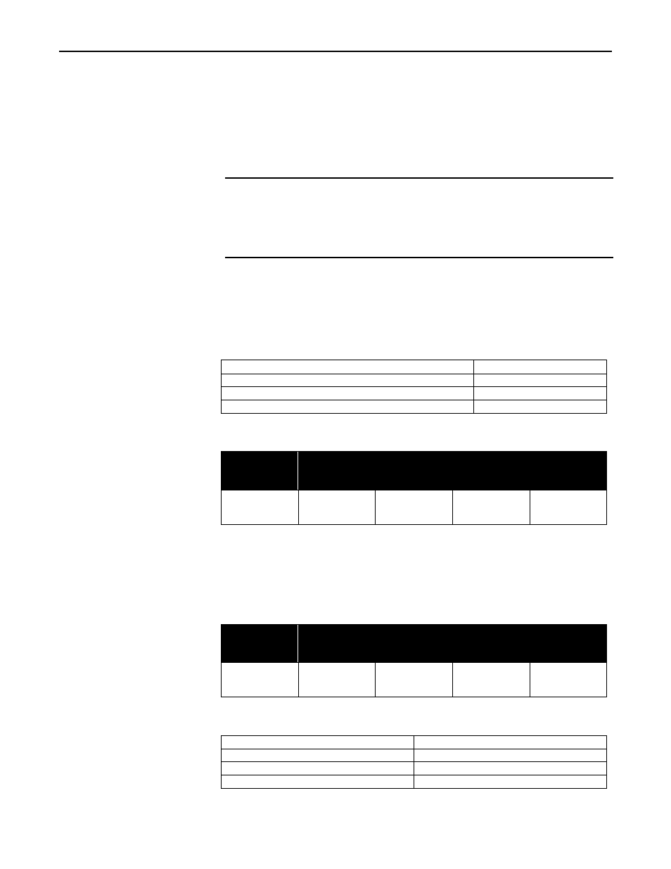
Wire Ratings:
Wire Temperature Rating:
75
°C or Higher
Line/Load Wiring Voltage Rating (240 VAC systems)
300 VAC Minimum
Line/Load Wiring Voltage Rating (480 VAC systems)
600 VAC Minimum
Allowable Wire Sizes:
Current
Rating of
System
Line
Connections
Load
Connections
Ground
Connection
Control
Circuit
Connections
120 Amp
160 Amp
#6-250 MCM
#6-250 MCM
#6-250 MCM
#6-250 MCM
#4-1/0 AWG
#4-1/0 AWG
22-10 AWG
22-10 AWG
Recommended Minimum Wire Sizes:
NOTE:
Wire temperature and connector ampacity ratings are based on NEC 310-16 using
75
°
C copper wire de-rated for 50
°
C ambient environment.
Current
Rating of
System
Line
Connections
Load
Connections
Ground
Connection
Control
Circuit
Connections
120 Amp
160 Amp
1 AWG
2/0 AWG
6 AWG
4 AWG
6 AWG
6 AWG
16 AWG
16 AWG
Electrical Inputs:
Heater open interlock switch
Contacts Rated for 120 VAC at 2.0 A
Cooling flow interlock switch
Contacts rated for 120 VAC at 100 mA
Heater over-temp. thermoswitch
Contacts rated for 120 VAC at 100 mA
Remote interlock switch
Contacts rated for 120 VAC at 100 mA